262
Detail program description - Control adjust
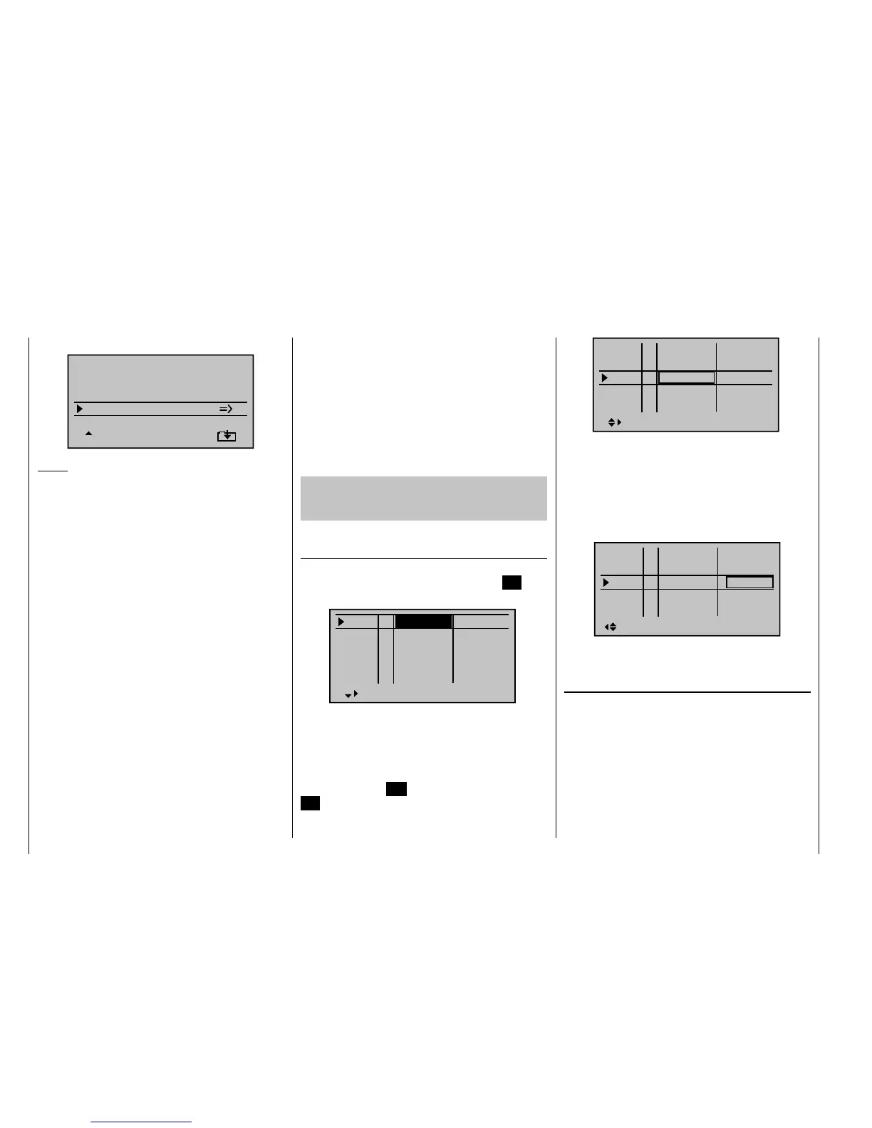
mixers" menu ...
Elevat curve
BRAKE SETTINGS
QR
Crow
D.red
+44%
+77%
0%
+66%
0%
+55%
WK WK2
Notice:
The "Brake settings" menu is switched "off" if "yes"
is entered for the currently active fl ight phase in the
"Model type" menu, page 82, "Motor to C1 front/rear"
and in the "Motor" column of the "Phase setting" menu,
page 128. If applicable, switch to the fl ight phase
Crow Further above we designated the C1 joystick
for the brake fl ap control.
In this line you determine the share with
which the AI and FL should be included
on actuation of C1 in the manner that both
ailerons are defl ected "slightly" upward and
both fl aps are defl ected as far downward as
possible.
By simultaneously pressing the keys of
the left touch pad, you switch to the "Servo
display" menu so that you can observe
the servo movement and, in particular, that
there is no infl uence on the fl aps above the
adjusted brake offset, e.g. +90 %, up to the
throw limit of the controller C1; see above
("Idle travel" of the C1 joystick).
D.red In the line "Differentiation reduction" you
should enter the value previously set in
the ailerons differentiation line in order to
suppress it again during braking.
Elevat curve In this line you set another correction
value for the elevator, see page 162.
Insofar as necessary, check and adjust all fl ap throws,
the servo center, the servo travel and the travel limitation
through the menu "Servo adjustment".
It may also be time to start the initial fl ight testing,
insofar as all global settings - that is to say, all fl ight-
phase independent settings - are completed.
Two additional fl ight phases should be set up in
the following, each of which requires a somewhat
different fl ap position.
Therefore, switch to the menu …
"Phase setting" (page 128)
… and activate the assignment of phase names in the
"Name" column by briefl y pressing the central
SET key
of the right touch pad:
Pha1
Pha2
Pha3
Name ph.Tim.
Pha4
Pha5
normal
Start
Strecke
–
–
–
–
Now give Phase 1 - the "Normal phase" - that is also
the phase which includes the previous settings, the
name "Normal", which you select with the arrow keys.
Phase 2 receives the name "Thermal" and Phase 3
receives the name "Speed". Now conclude your entry by
briefl y pressing the ESC key of the left touch pad or the
SET key of the right touch pad:
Pha1
Pha2
Pha3
Name ph.Tim.
Pha4
Pha5
Normal
Thermal
Speed
–
–
–
–
Now move the marking frame over the column "ph.Tim."
to the right to the column "Sw.time" and set a "switching
time" from any other phase to the respective phase in
order to avoid an abrupt phase change ; in other words
erratic changes of fl ap positions. Now try out different
switching times. In this example we have specifi ed 1 s in
each case:
Pha1
Pha2
Pha3
Name Sw.time
Pha4
Pha5
+
+
Normal
Thermal
Speed
–
–
1.0s
1.0s
1.0s
0.1s
0.1s
Now assign the corresponding switches for these fl ight
phases in the menu ...
"Phase assignment" (page 134)
… with which you can switch between the three phases.
Since no special priority is necessary, assign the switch
"C", for example, in the display and select one of the two
limit positions of one of the two three-stage switches,
CTRL 9 or 10 as the switch. Then move the selected
switch back to the center position, activate the switch
assignment under "D" and move the selected three-
stage switch from its center position to the other limit
position in order to: