7
21901443 R02 - 2016 Gravely Atlas JSV3000 / JSV6000 EFI Service Manual
© Copyright Ariens Company
7.5
BEARING CARRIER INSTALLATION
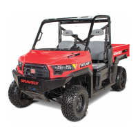
1. Install the end of the drive shaft through the backside
of the bearing carrier.
2. Install the upper and lower ball joint ends into the
front bearing carrier.
3. Install pinch bolts (A) and torque to specification.
TORQUE
Ball Joint Pinch Bolts:
42 lb-ft (57 Nm)
4. Install the steering tie rod end onto the front bearing
carrier and torque the fastener (B) to specification.
Install a NEW cotter pin (C)
TORQUE
Tie Rod End Fastener:
40 lb-ft (54 Nm)
5. Apply grease to the drive shaft splines.
6. Install front wheel hub assembly, cone washers, and
hand tighten the castle nut. Install washers with
domed side out.
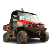
7. Install the front brake caliper. Install the mounting
bolts (D) and torque to specification.
TORQUE
Front Caliper Mounting Bolts:
30 lb-ft (41 Nm)
CAUTION
New bolts have a pre-applied locking agent which is
destroyed upon removal. Always use new brake caliper
mounting bolts upon assembly.
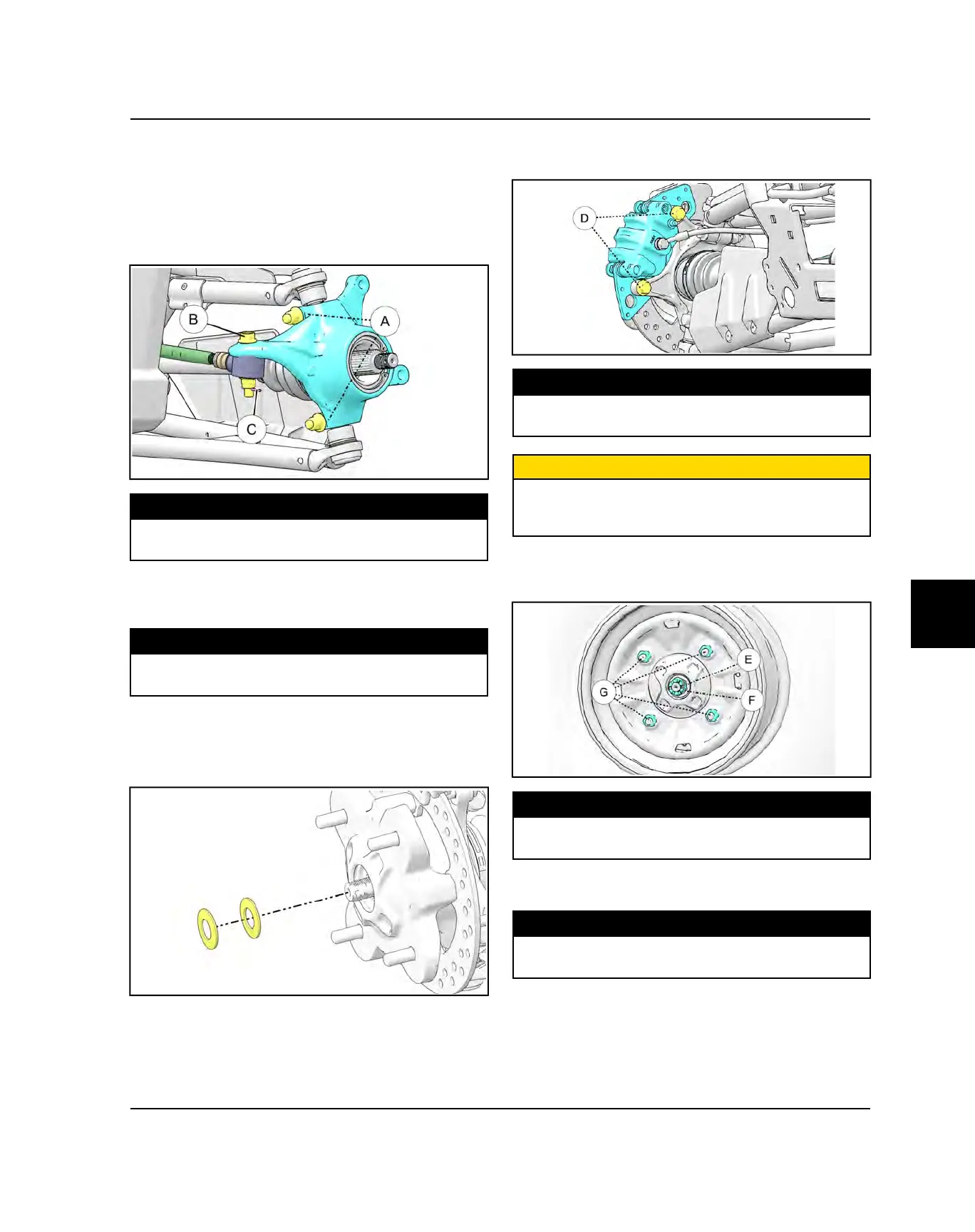
8. Torque wheel hub castle nut (E) to specification and
install a NEW cotter pin (F). Tighten nut slightly if
necessary to align holes for the cotter pin.
TORQUE
Front Hub Castle Nut:
75 lb-ft (102 Nm)
9. Install wheel and (4) wheel nuts (G). Torque wheel
nuts to specification.
TORQUE
Wheel Nuts (Steel):
60 lb-ft (81 Nm)
10. Rotate wheel and check for smooth operation. Bend
both ends of cotter pin around the end of the shaft.
Install the center cap and/or rubber dust cap.
FINAL DRIVE
 Loading...