8.24
21901443 R02 - 2016 Gravely Atlas JSV3000 / JSV6000 EFI Service Manual
© Copyright Ariens Company
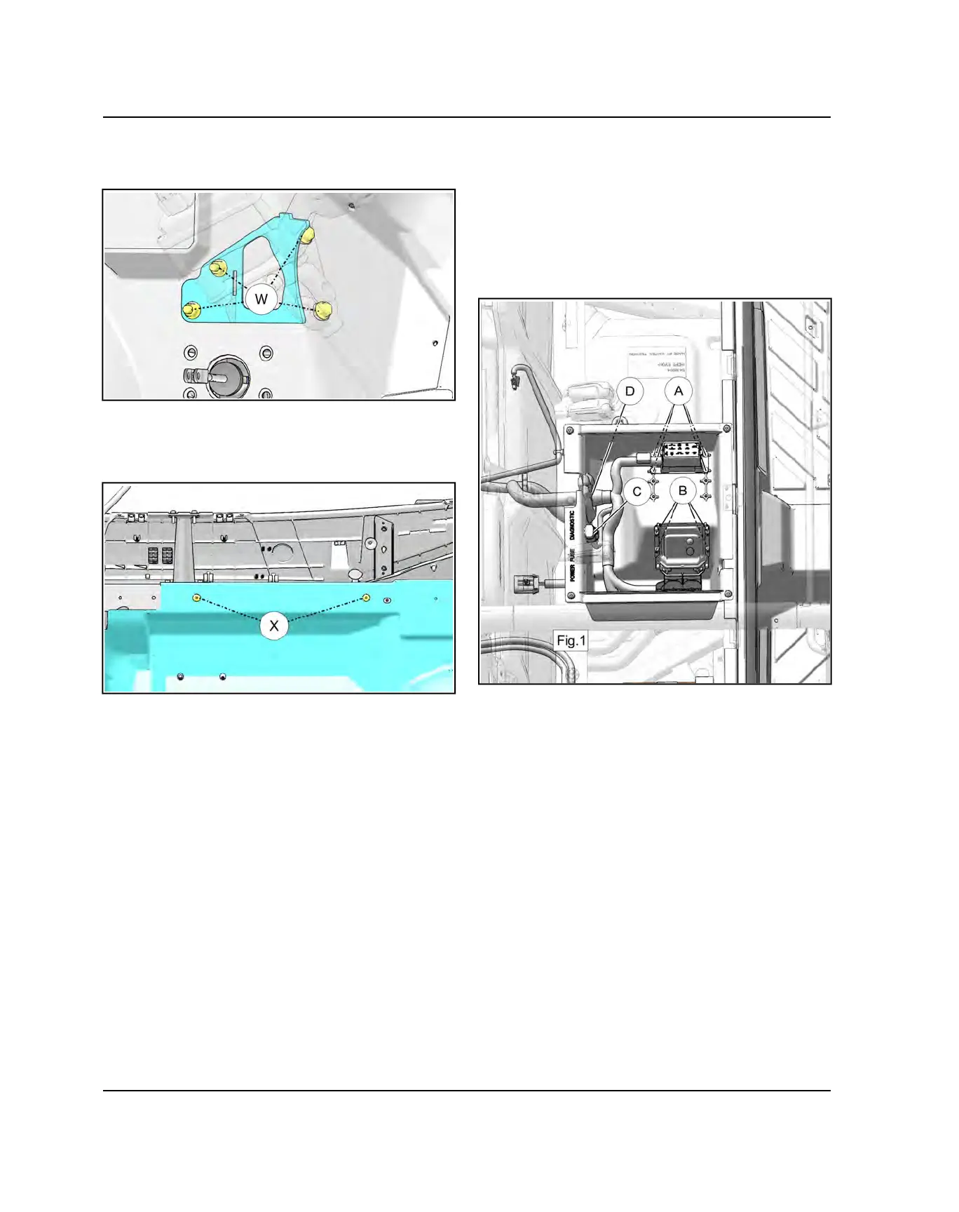
7. If equipped, remove the (4) fasteners (W) for the
EPS mount and remove the EPS unit and mount as
one.
8. Remove the lower steering shaft. Refer to “Steering
Shaft Removal”, page 8.27 procedure.
9. Remove (2) T-40 Torx-head screws (X) holding the
front floor to the frame.
10. Remove fasteners retaining the front floor to the front
fenders and cab frame mounts.
11. Remove the front floor from the vehicle.
REAR FLOOR REMOVAL - JSV6000
1. Remove both rear rocker panels. Refer to “Rocker
Panel Removal - CREW”, page 8.22 procedure.
2. Remove both front rocker panels. Refer to “Rocker
Panel Removal”, page 8.21 procedure.
3. Remove the battery.
4. Remove (4) T-25 Torx fasteners (A) Fig. 1 securing
the fuse box to the center under seat storage box.
5. Remove (4) T-25 Torx fasteners (B) Fig. 1 securing
the Electronic Control Unit (ECU) to the seat storage
box.
6. Remove the diagnostic connector (C) Fig. 1 from the
protective cover.
7. Remove the (4) T-40 Torx fasteners from the center
under seat storage box.
8. Remove the wire harness grommet (D) Fig. 1 to
separate the fuse box, ECU and diagnostic connector
wire harness from the storage box.
BODY / STEERING / SUSPENSION

 Loading...