22 1/02
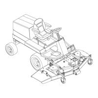
NOTE: Adjusting the neutral at operating temperature is
recommended.
1. Stop the engine, remove the ignition key, and lock the
brakes.
2. Raise the seat plate and loosen the hex nuts on the
neutral detent rod.
3. Loosen/tighten hex nuts to shift pump arm in
opposite direction of the creep. Make a small
adjustment. (One turn or less.)
4. Tighten the hex nuts.
5. Run the unit and check for creeping.
6. Repeat above steps as necessary.
TIRES AND WHEELS
Tires
Before each use, make a visual check of the tires. Check
tire pressure every 25 hours. See tire side wall for correct
air pressure.
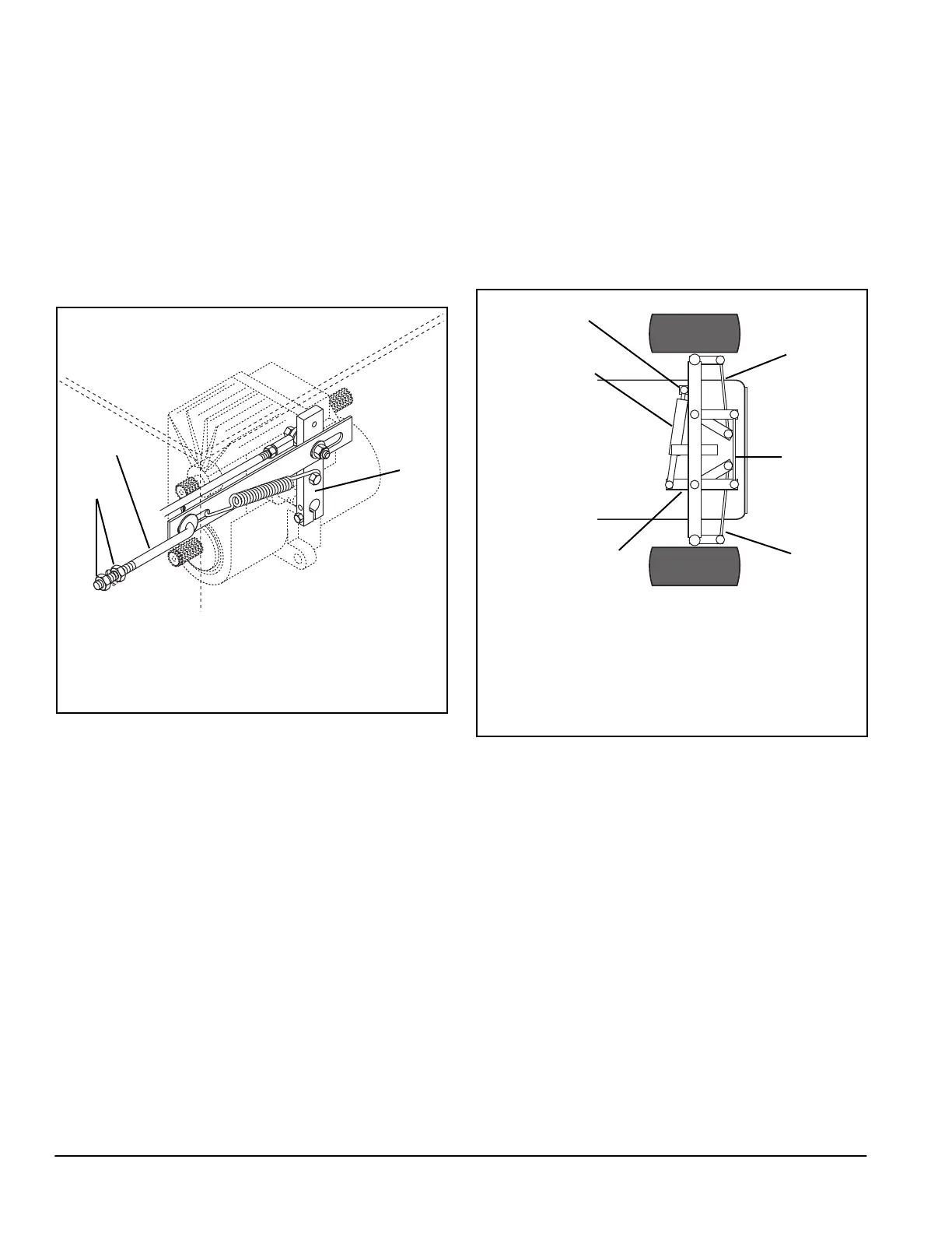
Wheel Alignment
Proper alignment of rear wheels is necessary to assure
proper steering and to reduce tire wear. Proper toe-in is
when the front of wheels are 1/16” to 1/8” closer together
than the rear of wheels, measured at horizontal center
line of rim flange.
If unit steering wanders or excessive tire wear develops,
toe-in should be checked.
Outer tie rods should be adjusted equally; the correct
length is 13.25" from bolt centers.
The correct length for the center tie rod is 12.75" from
bolt centers on two wheel models. On models with four
wheel assist, the correct distance is 12.12". The center
tie rod should not be used to make other adjustments.
To change toe-in (Figure 11):
1. Loosen jam nuts on the outer tie rods.
2. Turn outer tie rods to adjust toe-in.
3. Tighten jam nuts.
4. Turn the wheels to each side until the idler arms stop
against the tab on the center of the axle. If the idler
arms do not reach the tab, the steering cylinder is out
of adjustment.
To adjust the steering cylinder (Figure 11):
1. Turn wheels so that cylinder is extended.
2. On one end of steering cylinder, loosen jam nut on
rod end and remove hardware fastening rod end.
3. Fully extended cylinder and lock rear wheels to one
side.
4. Turn rod end until it aligns with hole in axle weldment
or steering arm.
5. Replace hardware and tighten jam nut.
1. Hex Nuts
2. Detent Rod
3. Pump Arm
Figure 10
1
3
2
OF0790
1. Outer Tie Rods
2. Center Tie Rod
3. Steering Cylinder
4. Axle Weldment
5. Steering Arm
Figure 11
5
4
2
OF0800
1
3
1