1/02
23
D
IRECTION
C
ONTROL
P
EDAL
IMPORTANT:
Correct adjustment of the direction control
pedal is necessary to prevent severe damage to the
hydrostatic transmission.
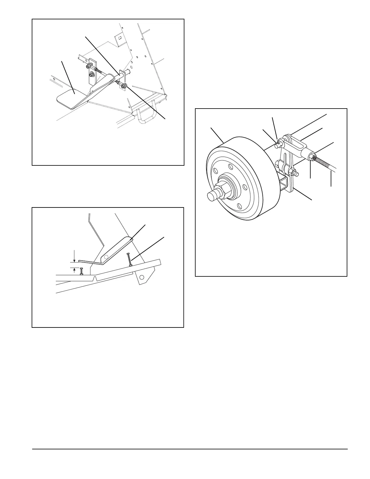
To adjust pedal (Figure 12):
1. Remove bolt connecting rod end to direction control
weldment.
2. Adjust rod end until pedal is at an angle which is
comfortable for the operator. Turn rod end
counterclockwise to move pedal angle toward
operator and clockwise to move pedal angle away
from operator.
3. Replace hardware holding rod end to direction
control weldment.
4. Adjust Control Pedal Stop Bolts
To adjust Pedal Stop Bolts (Figure 13):
1. Adjust Control Pedal to comfortable position as
above.
2. Set Forward Stop Bolt so pedal hits bolt at full
forward stroke.
B
RAKES
After each use of unit, wash dirt from brakes with water.
Each day before operation, inspect all parts and
fasteners. Repair or replace any missing, worn or
damaged brake or linkage parts. Tighten all nuts and
bolts.
Brake service is required if brakes do not stop and hold
unit effectively. Brakes should activated with 1/2”-3/4” of
foot pedal travel.
As necessary to compensate for brake lining wear, adjust
brake linkage as follows (Figure 14):
1. Stop unit on a level surface.
2. Stop engine and block wheels so unit cannot roll.
3. Remove cotter pin and clevis pin holding brake
control rod clevis to cam lever arm on the right
individual wheel brake. Loosen jam nut.
4. Turn clevis on brake control rod until correct
adjustment is achieved.
5. Fasten brake control rod clevis to cam lever arm with
clevis pin and cotter pin. Tighten jam nut.
6. Carefully test operation of right individual wheel
brake. If necessary, repeat above procedures to get
correct braking action.
7. Adjust left individual wheel brake as above so that
pedal travel is equal for both brakes.
IMPORTANT:
Replace brake shoes before lining is worn
to rivet heads.
If correct braking action cannot be achieved after
performing these procedures, do the following:
1
3
2
1. Direction Control Pedal
2. Rod End
3. Direction Control Weldment
Figure 12
OF1511
1. Pedal (Neutral Position)
2. Forward Stop Bolt
Figure 13
1
2
OF1480
1
4
3
2
5
6
7
Figure 14
OF0461
1. Brake
2. Clevis Pin
3. Cotter Pin
4. Brake Control Rod
Clevis
5. Jam Nut
6. Brake Control Rod
7. Cam Lever Arm