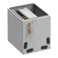
EasyManuals Logo

Gree FLEXX Series Installation Manual

Gree FLEXX Series
19 pages
To Next Page IconTo Next Page
To Previous Page IconTo Previous Page
Page #10 background imageLoading...
Page #10 background image
A-Coil
6
When installing in an area directly over a finished ceiling (such as an attic), an
emergency drain pan is required directly under the unit. See local and state codes for
requirements. When installing this unit in an area that may become wet, elevate the unit
with a sturdy, non-porous material. In installations that may lead to physical damage (i.e.
a garage) it is advised to install a protective barrier to prevent such damage.
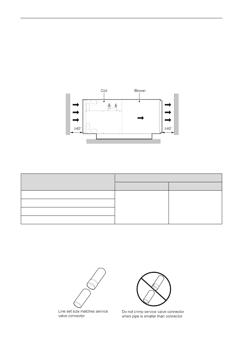
It is necessary to allow a minimum of 40between the inlet/outlet of the indoor unit
and wall, as shown below.
4.3 Piping Work
4.3.1 Specification of Connection Pipe
Model
External diameter (inch)
Gas pipe
Liquid pipe
Φ3/4 Φ3/8
4.3.2 Piping Preparation
4.3.2.1 Solder Connection
All cut ends are to be round, burr free, and cleaned. Failure to follow this practice
increases the chances for refrigerant leakage.
FLEXX24C
FLEXX36C
FLEXX48C
FLEXX60C

Other manuals for Gree FLEXX Series

Questions and Answers:

Question and Answer IconNeed help?

Do you have a question about the Gree FLEXX Series and is the answer not in the manual?

Gree FLEXX Series Specifications

General IconGeneral
TypeHeat Pump
SeriesFLEXX
SEERUp to 20
HSPFUp to 10
RefrigerantR410A
Heating Operation Range-22°F to 75°F
Cooling Operation Range5°F to 122°F
Operating Temperature Range (Heating)-22°F to 75°F
Operating Temperature Range (Cooling)5°F to 122°F
Energy Efficiency Ratio (EER)Up to 12.5
Dimensions (Outdoor Unit)Varies by model
Weight (Outdoor Unit)Varies by model
Compressor TypeInverter
Power Supply208/230V, 1Ph, 60Hz
Noise LevelAs low as 55 dB(A)

Related product manuals