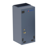
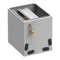
A-Coil
A stable connection is required between the coil and the blower to prevent
dumping.
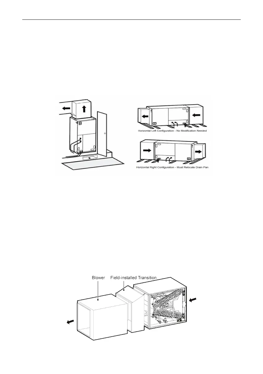
Based upon the actual conditions, if coil is installed as Fig (A), the coil should be
concealed in a specific room or space and make sure the coil is not accessible to the
general public.
Based upon the actual conditions, if coil is installed as Fig (B), make sure that there
is enough space for care and maintenance. And the coil is not accessible to the general
public.
(A) (B)
Based upon the actual conditions, Multi-Position A-Coils come factory installed
with a vertical and horizontal drain pans and can be configured for upflow or horizontal
pull-through installations.
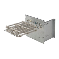
When the coil matches blower, the side which is nearby from coil is NOT allowed to
install electric heater kit. Recommended configuring is as shown below.
(a) Standard Application: Left hand shown / Right hand similar (not shown)
(b) Counter flow: Right hand shown / Left hand similar (not shown)
(c) Upward flow
(d) Downward flow
(a)
 Loading...