60
DC Inverter Multi
VRF Service Manual
PDFKLQHPLJKWFDXVH¿UHDFFLGHQWV
To ensure correct drainage of water, the drainage hose shall be installed according to the installation
instructions. Also the heat insulation shall be provided to avoid condensing.Improper installation of the pipe
might result in water leakage and lead to possible wetting of the articles in the room.
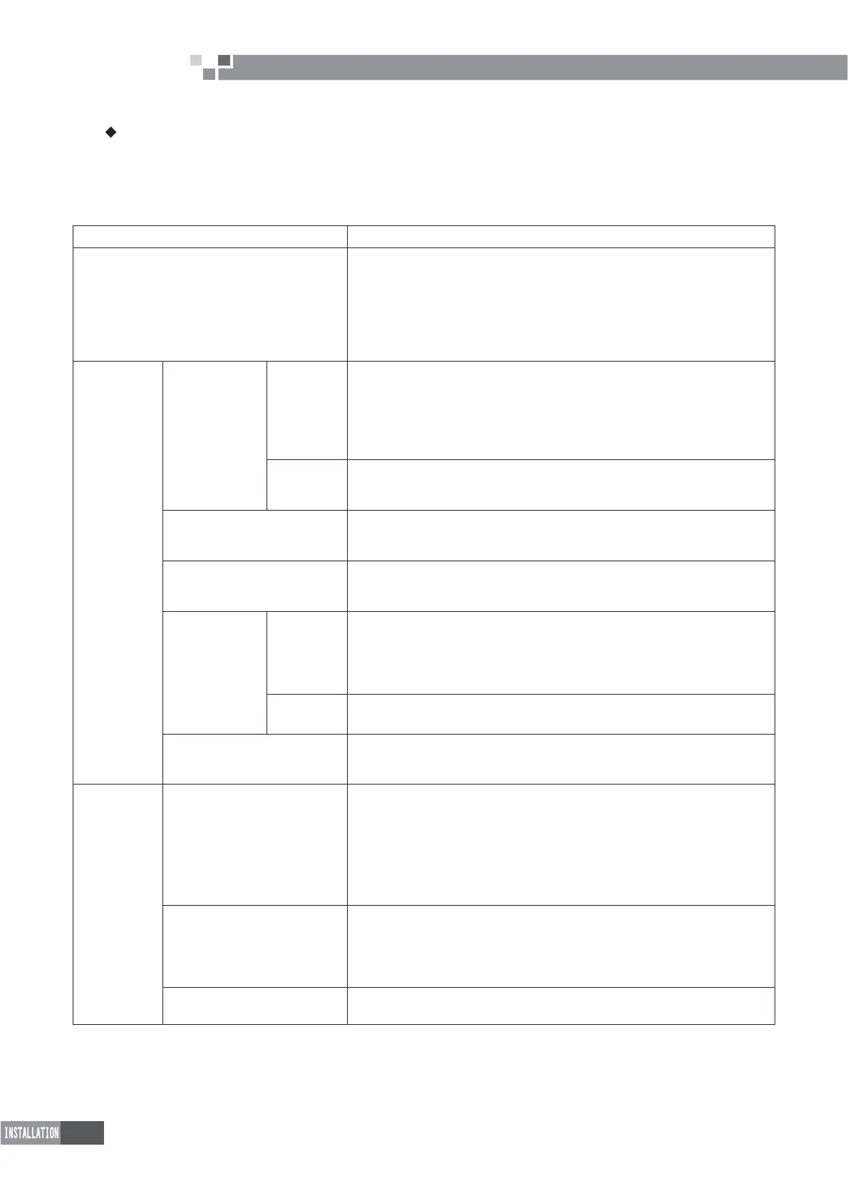
1.2 Key Points of Installation
Installation Procedures Description and Acceptance Criteria
Material Selection and Equipment Inspection
7KHPDWHULDOVVSHFL¿HGRQWKHHQJLQHHULQJGUDZLQJVKDOOEH
SXUFKDVHGDVVSHFL¿HGHJFRSSHUWXEHWKHUPDOLQVXODWLRQ
tube, PVC pipe, power cables, air switch, etc);
7KHPDWHULDOVQRWVSHFL¿HGRQWKHHQJLQHHULQJGUDZLQJVKDOOEHSXUFKDVHG
according to the actual quantity of works (e.g. hanger frame, cable duct, etc);
Check if the outdoor unit, indoor unit, communication
wires and accessories are complete.
Installation of
indoor unit
Communication
wire
Connection
The power cables shall be separated from communication
wires at a least distance of 10cm.
To avoid breaking the communication wires, please do not use strong force.
For multiple units, please mark them properly.
Switch on indoor and outdoor unit, and ensure there is
no display of “Communication Wire Error E6”
Address
dial code
Each indoor unit under the same system has a unique address dial code.
The wired controller and its corresponding indoor
unit have the same address dial code.
Remote Control
Select the remote control mode;
The centralized controller and communication module shall
be installed free from the source of interference.
Power cord
7KHSRZHUFDEOHPXVWPHHWWKHVSHFL¿FDWLRQV
The indoor units under the same system must be
DUUDQJHGXQGHUXQL¿HGSRZHUVXSSO\
Drainage hose
Installation
7KH39&SLSHVPXVWPHHWWKHVSHFL¿FDWLRQV
$VSHFL¿FJUDGLHQWPXVWEHSURYLGHGDORQJWKHZDWHUÀRZGLUHFWLRQ
Carry out water detection after installation.
Carry out thermal insulation to the drainage hose only
after the water detection is accepted.
Thermal
insulation
7KHWKHUPDOLQVXODWLRQWXEHPXVWPHHWWKHVSHFL¿FDWLRQV
Seal between the thermal insulation pipes to avoid air entry.
Installation of Air Duct
(when with high static
pressure duct-type unit)
Design the length of air duct according to static pressure;
The return air inlet shall be optimally designed to avoid too small size.
Installation of
connection
pipes
Welding
7KHFRSSHUWXEHPXVWPHHWWKHVSHFL¿FDWLRQV
Ensure it is dry and clean inside the tube.
Make sure to charge nitrogen as required for protection when welding the tubes.
Please keep to the welding process and ensure the system free of leakage.
$GGDGXDOZD\¿OWHURQOLTXLGSLSHVLGH
For multiple systems, please mark them properly.
Carry out leakage detection under pressure after welding.
Purge and make leakage
detection under pressure
Purge the system clean.
Keep the pressure for 24 hours
([FHSWIRUWKHLQÀXHQFHE\WHPSHUDWXUHLWLVGHHPHGDFFHSWDEOH
if pressure drop is within 0.02MPa. (With the temperature change
by 1?, the pressure will change by approx. 0.01MPa).
Thermal insulation
7KHWKHUPDOLQVXODWLRQWXEHPXVWPHHWWKHVSHFL¿FDWLRQV
Seal between the thermal insulation pipes to avoid air entry.
 Loading...