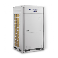
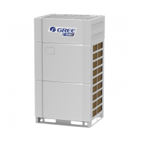
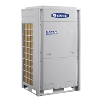
GREE Photovoltaic Direct-driven Inverter Multi VRF Units
99
Master module must be set correctly; otherwise units cannot be started up.
1.3.1.9 DIP Switch Example
(1) Explanation of DIP switch positions
On the DIP switch, “ON” indicates “0” status and the opposite direction indicates "1” status.
The position of white lever indicates the position to be set to.
White lever
position
"0" status "1" status
White lever
position
ON ON
(2) Example
The following takes master unit settings as an example. Assume that a system consists of three
modules: module a, module b, and module c. Set module c to master unit and the other two modules to
sub-modules. The settings are as follows:
1.3.2 System Function Button Operations
Module c (master module) Modules a and b (submodules)
White lever
position
White lever
position
ON
0 0
SA8_MASTER-S
White lever
position
White lever
position
ON
1 0
SA8_MASTER-S
Note:
① System function settings and query must be performed after commissioning of the entire unit.
② System function settings and query can be used no matter whether the entire unit runs.
1.3.2.1 Introduction to Function Buttons
When function buttons are used to set function
s for outdoor unit, the cover of electric box and
panel must be assembled well. Setting can only be done through the maintenance window. Otherwise,
electric shock may occur.
The main board AP1 of the ODU consists of eight function buttons:

 Loading...


