GREE Photovoltaic Direct-driven Inverter Multi VRF Units
281
3.2.3 Replacement and Notice for Compressor Drive Module
Step 1: Make sure power is disconnected. Set a multimeter to AC voltage gear and measure voltage
between two of the lines (L1, L2, L3). Continue the following steps as long as each result is 0V
(Sometimes, a multimeter may have error and reads other than 0V). Set a sign beside the power supply
for warning.
Step 2: Measure compressor drive DC bus voltage between P and N. Set the multimeter to DC
voltage gear and measure the voltage between P and N. The voltage should be lower than 36V. If no
multimeter is available, wait for 20 minutes on the condition that power is off. Then you may proceed with
the following steps.
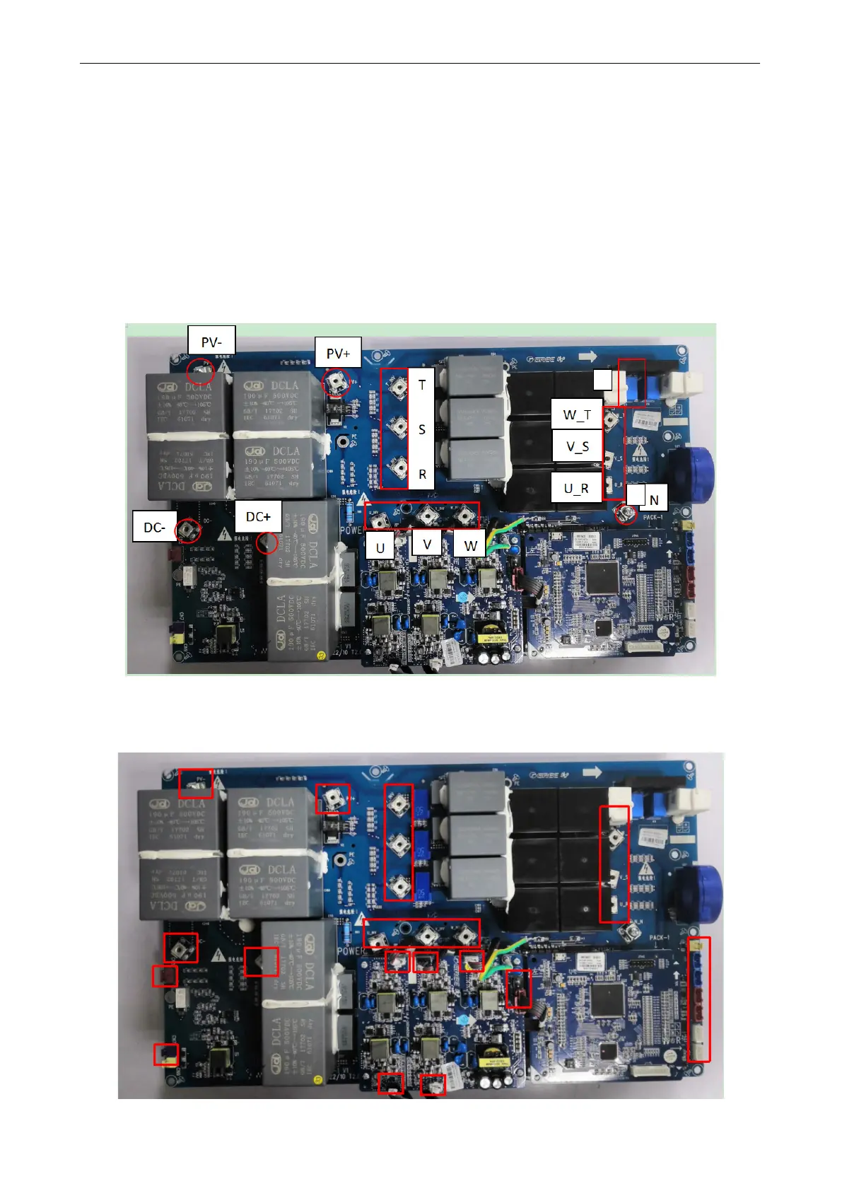
Step 3: Disconnect all the cables from the compressor drive module. Including photovoltaic pad PV
+, PV-,Three-phase AC pad R_INV, S_INV, T_INV, U_INV, V_INV, W_INV, W_T, V_S, U_R, DC bus pad
DC +, DC-,Signal pad CN5, 6, 7, 8, 9, 10, 11, 12,Drive power pad CN13, 14, 15, 16, 17, 18.
 Loading...


