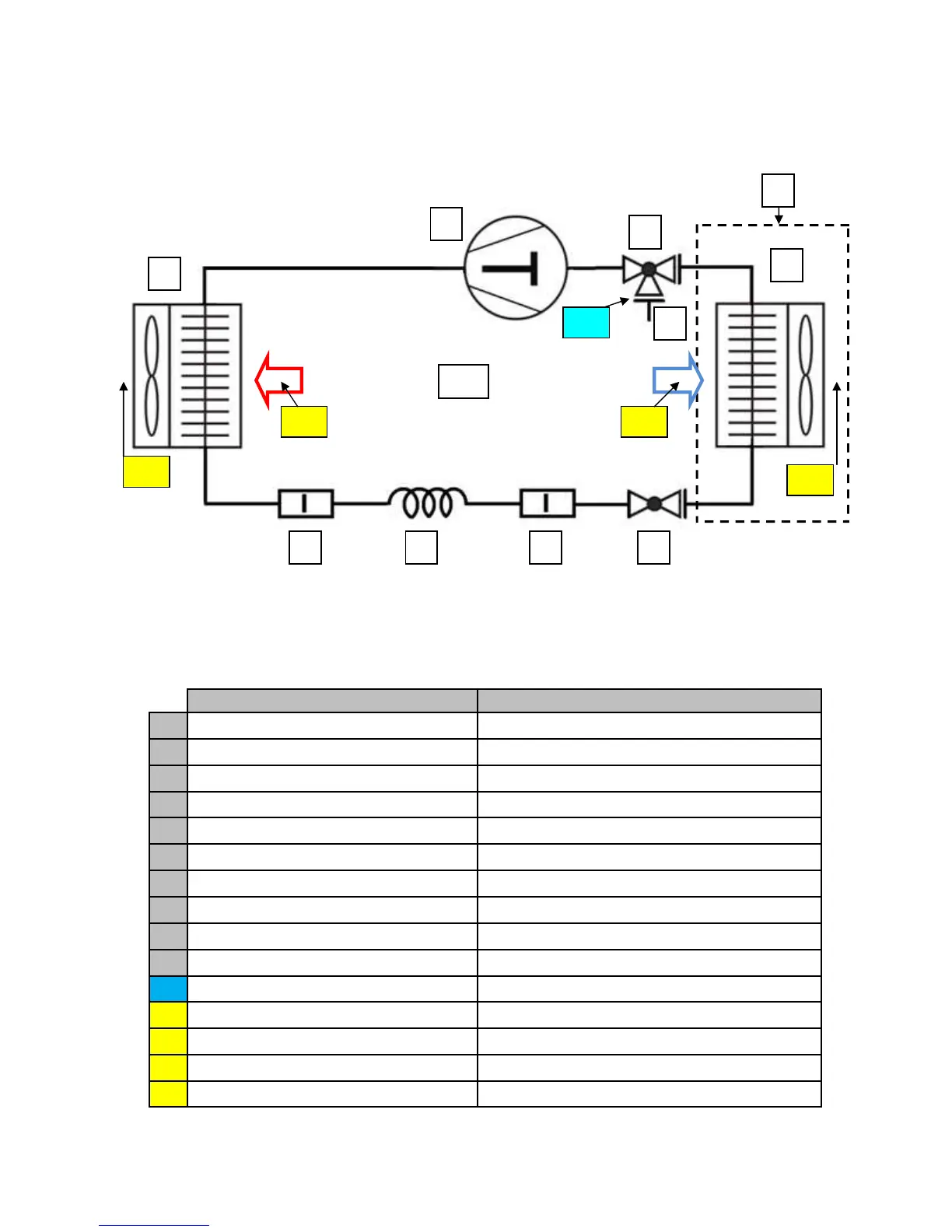
Refrigerant Flow Diagram
Designation Remark
1 Compressor Rotary scroll
2 Condenser Finned Heat Exchanger
3 Evaporator Finned Heat Exchanger
4 Capillary tube Refrigerant expansion device
5 Strainer Refrigerant filtering device
6 2 - way valve Stop valve
7 3 – way valve Stop valve and ¼” SAE service port
9 Indoor unit Pre-assembled with 5 m refrigerant transfer pipes
10 Outdoor unit
P1 Suction pressure R-290 low pressure gauge measuring
T1 Temperature Air- inlet Room air entering evaporator
T2 Temperature Air- outlet Room air leaving evaporator
T3 Temperature Air- inlet Outside air entering the condenser
T4 Temperature Air- outlet Outside air leaving the condenser
8 Service Port 1/4” NPT
P1
T1 T3
T4
T2
5 4 5
2
1
7
9
3
6
10
8
 Loading...