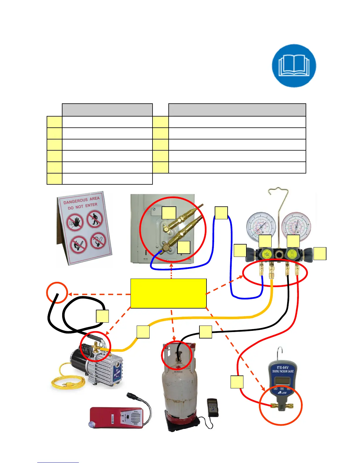
Arrangement of Equipment and Tools
The drawing below indicates the arrangement of equipment and tools for service
work where flammable refrigerant can be present. The interconnection with re-
frigerant transfer hoses is also shown. Capital letters designate the specific
valve or refrigerant hose. Within the following pages are these letters again in
the course of activity sequences to be carried out for specific service activities
like charging of refrigerant or evacuation of the system. If specific valves have to
be activated or refrigerant hoses to be connected, the letter indicates the posi-
tion in the diagram for reviewing and better understanding.
Valve
Refrigerant Hose
A
Manifold Low Pressure Gauge
E
Connection Hose A > L
B
Manifold Vacuum Pump
F
Connection Hose B > Vacuum Pump
C
Manifold Refrigerant Cylinder
G
Connection Hose C > R-290 Cylinder
D
Manifold (Vacuum Gauge)
I
Connection Hose D > Vacuum Gauge
H
Outdoor Unit Liquid Side (High)
K
Vent Hose 5 m length ½” (12 mm) inner diameter
L
Outdoor Unit Gas Side (Low)
Temporary
Flammable Zones
H
L
B
A
C
D
I
E
K
F G