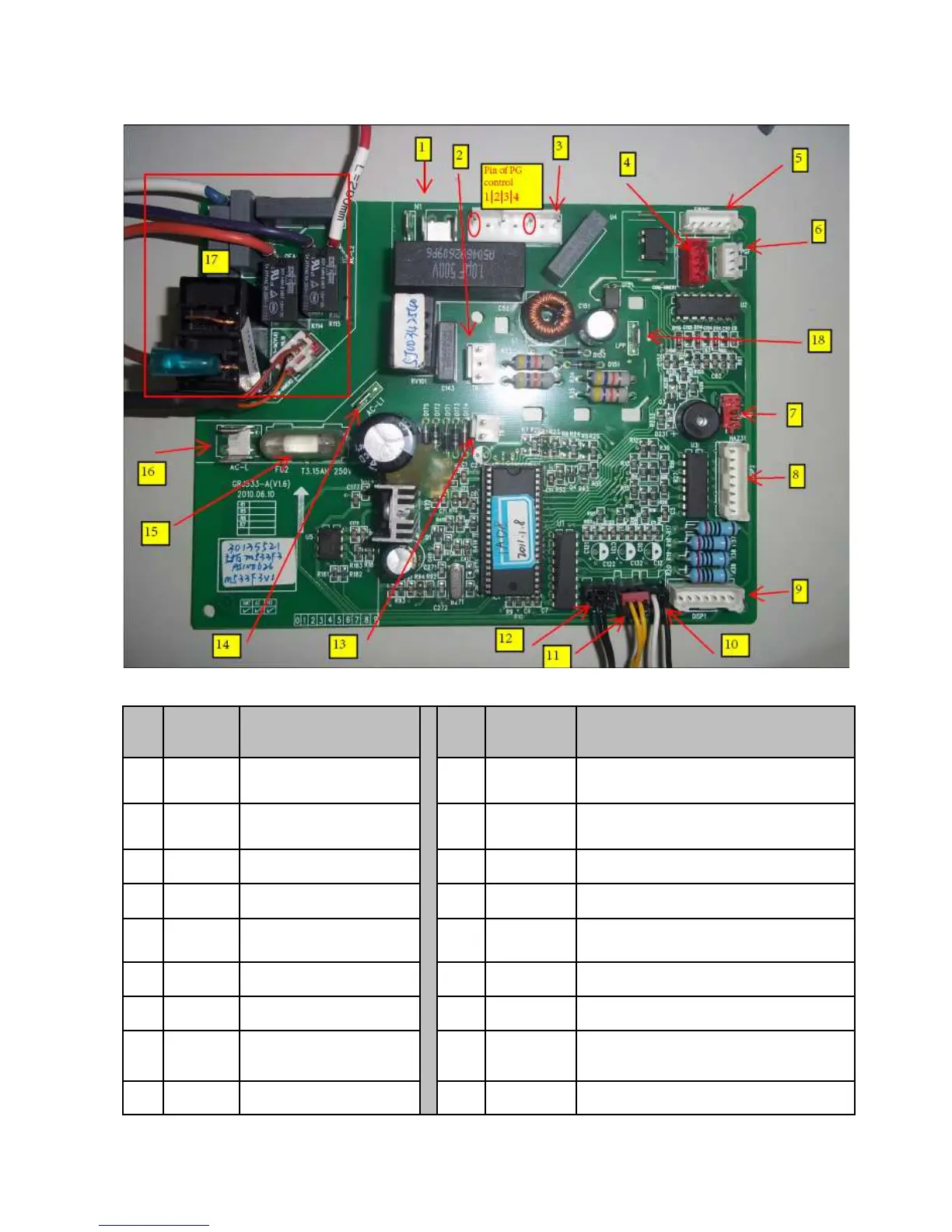
Printed Circuit Board (top-view)
No. Interface Name
No. Interface Name
1 Neutral wire of PCB 10 Outdoor ambient temperature sensor
2
Transformer input
terminal
11 Indoor ambient temperature sensor
3 PG motor control 12 Indoor tube temperature sensor
4
Relay box control
13 Transformer output terminal
5 Swing motor control 14 Live wire input terminal of relay box
6 PG motor feedback 15 Fuse
7 Jumper cap 16 Live wire input
8 Display connector 2 17
PCB indoor unit relay box
9 Display connector 1 18 Low pressure switch
Name
on PCB
board
N, N1
TR-IN
PG
COM—
INNER1
SWING
PGF
JUMP
DISP2
DISP1
Name
on PCB
board
OUTROOM
ROOM
TUBE
TR-OUT
AC-L1
FU2
AC_L
/
LPP