High Volume, Low Speed Ceiling Fans 9
®
4. Torque hardware to 80 ft∙lbf (108.5 N∙m).
5. Turn to page 10 to continue with Motor/Hub to
Downtube Installation.
Z-Purlin Mounting Kit
Components required from Bag # 915431:
• Z-Purlin Backing Plate (2)
• Z-Purlin Mounting Bracket (2)
• 1/2 in. – 13 x 1¾ in. Grade 8 Hex Bolt (20)
• 1/2 in. – 13 Grade 8 Nylon Locknut (20)
• 1/2 in. Washer (40)
Hardware/Tools Needed (Not Included):
• Structural Steel Angles (2)
• Torque Wrench
• 3/4 in. Socket and Wrench
• 3/4 in. Wrench
• Drill and 9/16 in. Drill Bit
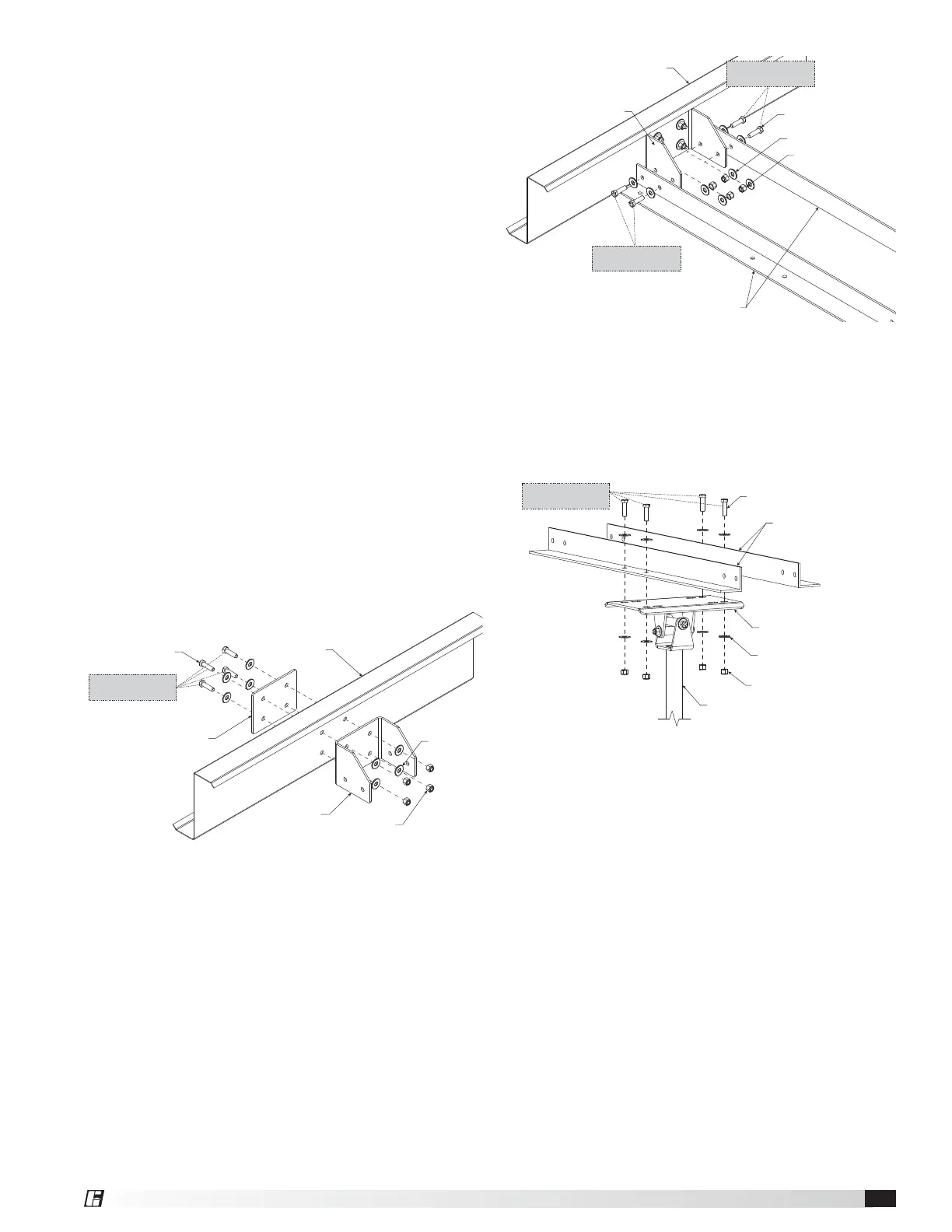
1. Locate desired fan hanging location. Using the
supplied z-purlin mounting brackets as templates,
mark and drill (4) 9/16 in. holes in each z-purlin.
2. Mount z-purlin mounting brackets and backing
plates using supplied (8) 1/2 in. – 13 x 1¾ in. grade
8 hex bolts, (16) 1/2 in. washers, and (8) 1/2 in.
– 13 grade 8 nylon locknuts. Torque hardware to
80ft∙lbf (108.5 N∙m).
Z-PURLIN
BACKING PLATE
1/2 in. - 13 x 1-3/4 in.
GRADE 8 HEX BOLT
Z-PURLIN
1/2 in. WASHER
Z-PURLIN MOUNTING
BRACKET
1/2 in. - 13 GRADE 8
NYLON LOCKNUT
TORQUE TO 80 FT∙LBF
(108.5 N∙m)
3. Size structural steel angles (by others) to fit within
z-purlins and installed z-purlin mounting brackets.
Size of angle to be determined by structural
engineer.
4. Bolt structural steel angles in place using supplied
(8) 1/2 in. – 13 x 1¾ in. grade 8 hex bolts, (16)
1/2 in. washers, and (8) 1/2 in. – 13 grade 8 nylon
locknuts. Torque hardware to 80 ft∙lbf (108.5 N∙m).
STRUCTURAL STEEL ANGLES
(BY OTHERS)
1/2 in. - 13 x 1-3/4 in.
GRADE 8 HEX BOLT
Z-PURLIN
1/2 in. WASHER
Z-PURLIN BRACKET
1/2 in. - 13 GRADE 8
NYLON LOCKNUT
TORQUE TO 80 FT∙LBF
(108.5 N∙m)
TORQUE TO 80 FT∙LBF
(108.5 N∙m)
5. Using the universal mounting plate as a template,
mark and drill (4) 9/16 in. holes in structural steel
angles.
6. Align the universal mounting plate and bolt into
place using (4) 1/2 in. – 13 x 1¾ in. grade 8 hex
bolts, (8) 1/2 in. washers, and (4) 1/2 in. – 13 grade
8 nylon locknuts. Torque hardware to 80 ft∙lbf
(108.5 N∙m).
STRUCTURAL STEEL ANGLES
(BY OTHERS)
1/2 in. - 13 x 1-3/4 in. GRADE 8 HEX BOLT
DOWNTUBE & MOUNT ASSEMBLY
1/2 in. WASHER
UNIVERSAL MOUNTING PLATE
1/2 in. - 13 GRADE 8 NYLON LOCKNUT
TORQUE TO 80 FT∙LBF
(108.5 N m)
7. Turn to page 10 to continue with Motor/Hub to
Downtube Installation.
Unistrut
®
Mounting Kit (By Others)
Hardware/Tools Needed (Not Included):
• Unistrut
®
Channels
• Unistrut
®
and Fan Installation Hardware
1. Size Unistrut channels (by others) to span the
required distance between structural members
of the building. Size of Unistrut channels
and appropriate installation hardware to be
determined by structural engineer. Contact
Unistrut customer support (www.unistrut.us) for
product recommendations and detailed installation
instructions for Unistrut products.
2. Install Unistrut channels per the manufacturer’s
recommendations.
3. Locate desired hanging location for the fan.
4. Bolt universal mounting plate to Unistrut channels
with the appropriate hardware as identified by
structural engineer. Torque to 80 ft∙lbf (108.5 N∙m).