Greenlee Textron / Subsidiary of Textron Inc.
19
4455 Boeing Dr., Rockford, IL 61109-2988 815/397-7070
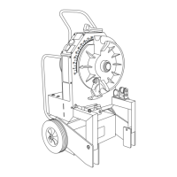
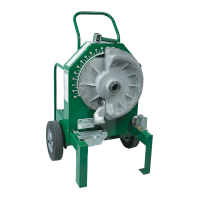
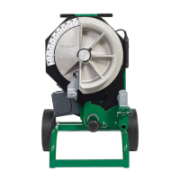
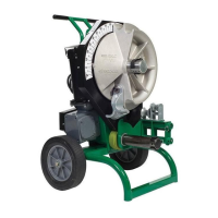
555BAT™ Battery-Powered Bender
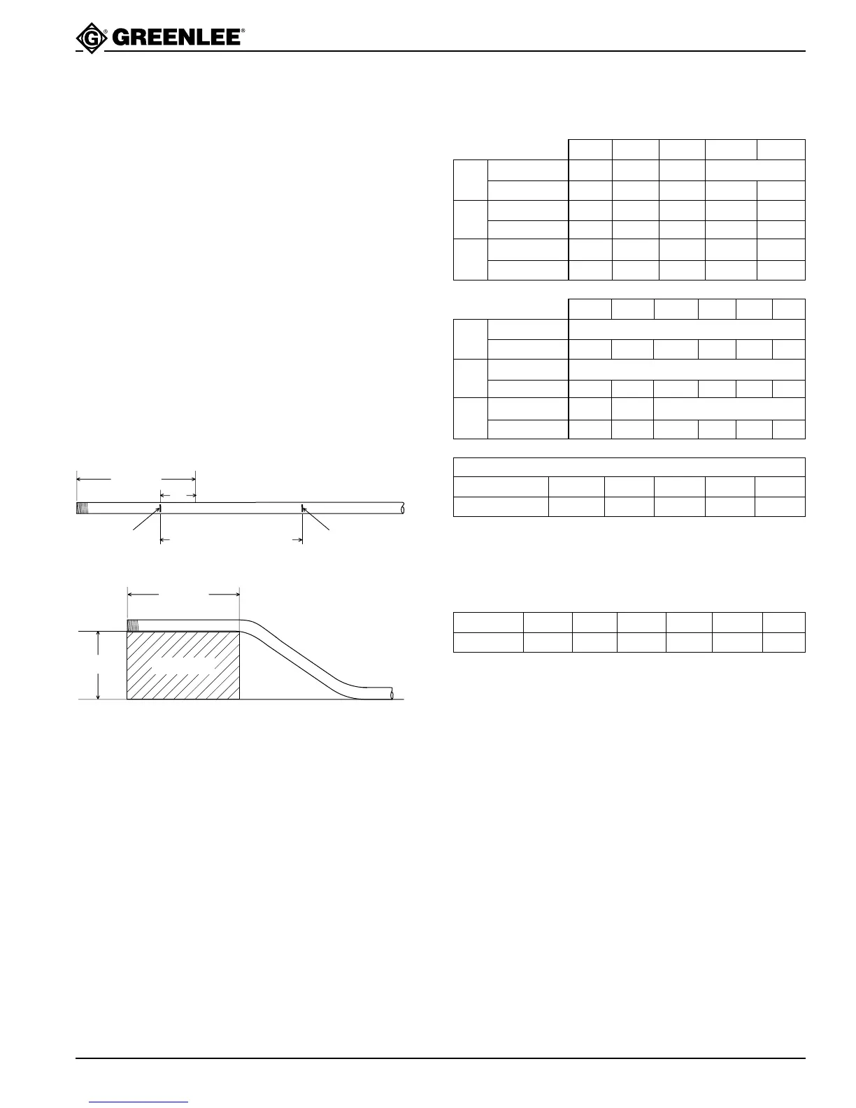
CENTER-TO-CENTER DISTANCE = OFFSET HEIGHT x MULTIPLIER
OFFSET ANGLE 10° 15° 22-1/2° 30° 45°
MULTIPLIER 5.8 3.9 2.6 2.0 1.4
Figures are approximate
OFFSET ➤ 12 14 16 18 20 22
Max Conduit Size 2
Center-to-Center 46-3/8 54-1/16 61-13/16 69-9/16 77-1/4 85
Max Conduit Size 2
Center-to-Center 24 28 32 36 40 44
Max Conduit Size 1-1/2 2 2
Center-to-Center 16-15/16 19-13/16 22-5/8 25-7/16 28-1/4 31-1/8
OFFSET ➤ 246810
Max Conduit Size 3/4 1-1/2 2 2
Center-to-Center 7-3/4 15-7/16 23-3/16 30-15/16 38-5/8
Max Conduit Size 3/4 1 1-1/2 2
Center-to-Center 8 12 16 20
Max Conduit Size 1/2 1 1-1/4
Center-to-Center 8-1/2 11-5/16 14-1/8
Offsets
1. Measure the height and length of the obstruction.
Select the angle to be used.
2. See the Minimum Offset section of the Offset Table.
The height of the obstruction must be equal to or
greater than the Minimum Offset.
3. Refer to the X Table to find the X dimension. Refer
to the Offset Table to find the Center-To-Center
Distance.
Note: If the center-to-center distance is not
shown, calculate it by using the multipliers
shown in the Offset Table.
4. Mark the conduit as shown.
5. Insert the conduit into the bender. Align Mark 1 with
the front edge of the hook and bend the conduit.
6. Align Mark 2 with the front edge of the hook. With-
out removing the conduit from the bender, rotate the
conduit 180°. Make the second bend.
Bending Instructions (cont’d)
15°
30°
45°
15°
30°
45°
Offset Table
LENGTH
HEIGHT
LENGTH
MARK 1 MARK 2
CENTER TO CENTER
DISTANCE
“X”
OBSTRUCTION
X Table
CONDUIT SIZE 1/2 3/4 1 1-1/4 1-1/2 2
“X” 3-1/16 3-1/16 3-3/16 4 4-1/4 4-1/2
Figures are approximate