11
W450311 Rev C 2/13
2.4.2.4 Check Pressure Sensors
There are two pressure sensors installed as part of the system. Both pressure sensors are mounted
within the computer unit. One is connected to the piston side of the boom hoist cylinder via flexible hose;
the other is connected to the rod side of the boom hoist cylinder via flexible hose. Both hoses are
protected by velocity fuses within the boom hoist cylinder valve block on the end of the cylinder.
The pressure sensor located on the piston side, is subject to the hydraulic pressure needed to support
the weight of the boom, any attachments, and the load. The pressure sensor on the rod side monitors
the pressure necessary to control the down motion of the boom. The computer unit uses this
information (along with other sensors such as extension, length, and angle), to compute the weight of
the suspended load. The maximum continuous working pressure for the sensors is 250 bar (3625 PSI).
The pressure sensing system is calibrated at the factory. Pressure sensors may not be individually
replaced. Any serious problem will necessitate changing the entire computer unit.
1. Lower the boom until the boom hoist cylinder is fully retracted and on its stop.
2. Loosen the hydraulic connections to the pressure sensors to ensure zero pressure is present on
the sensors.
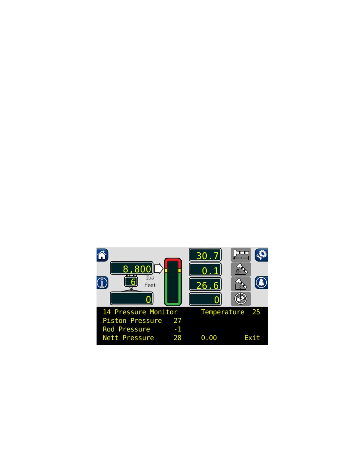
3. Enter the calibration mode and press “Menu Up” to access “14 PRESSURE MONITOR” to view
both sensor pressures and net pressure.
4. Check the pressure values of both sensors. The pressure values should be between -75 and
+75 PSI. If not, replace the computer unit.
5. Check the nett pressure values of both sensors. This should be between -35 and +35 psi. If not,
replace the computer unit.
WARNING!
BOTH PRESSURE SENSORS ARE PRE-CALIBRATED FROM THE FACTORY AND
SUPPLIED AS PART OF THE COMPUTER. THE PRESSURE SENSORS MAY NOT BE
REPLACED. REMOVAL OR REPLACEMENT OF THE PRESSURE SENSORS FROM THE
COMPUTER INVALIDATES THE WARRANTY AND WILL ADVERSELY AFFECT THE
PRESSURE CALIBRATION.
 Loading...