20
W450311 Rev C 2/13
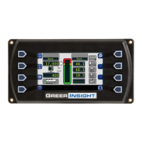
5.3 Calibration Menus
After entering the calibration menu, press the “Menu Up” button until “02 Zero Sensors” is reached.
Scroll through the menu options by pressing the “Menu Up” or “Menu Down” buttons. To select an item,
press the button adjacent to the menu listing as shown in the example.
The main menu items used to calibrate the system are:
• 02 Zero Sensors
• 03 Span Sensors
• 04 Swing Potentiometer
The only calibrations needed are for the boom extension function and the boom angle function. They
must be properly set to zero. On machines with string potentiometer style outrigger position sensors, if
a sensor is replaced, it will need to be calibrated. Refer to CALIBRATING THE OUTRIGGER
POSITION SENSOR.
The system is also equipped with a swing potentiometer. This is designed to track the turret in relation
to the chassis.
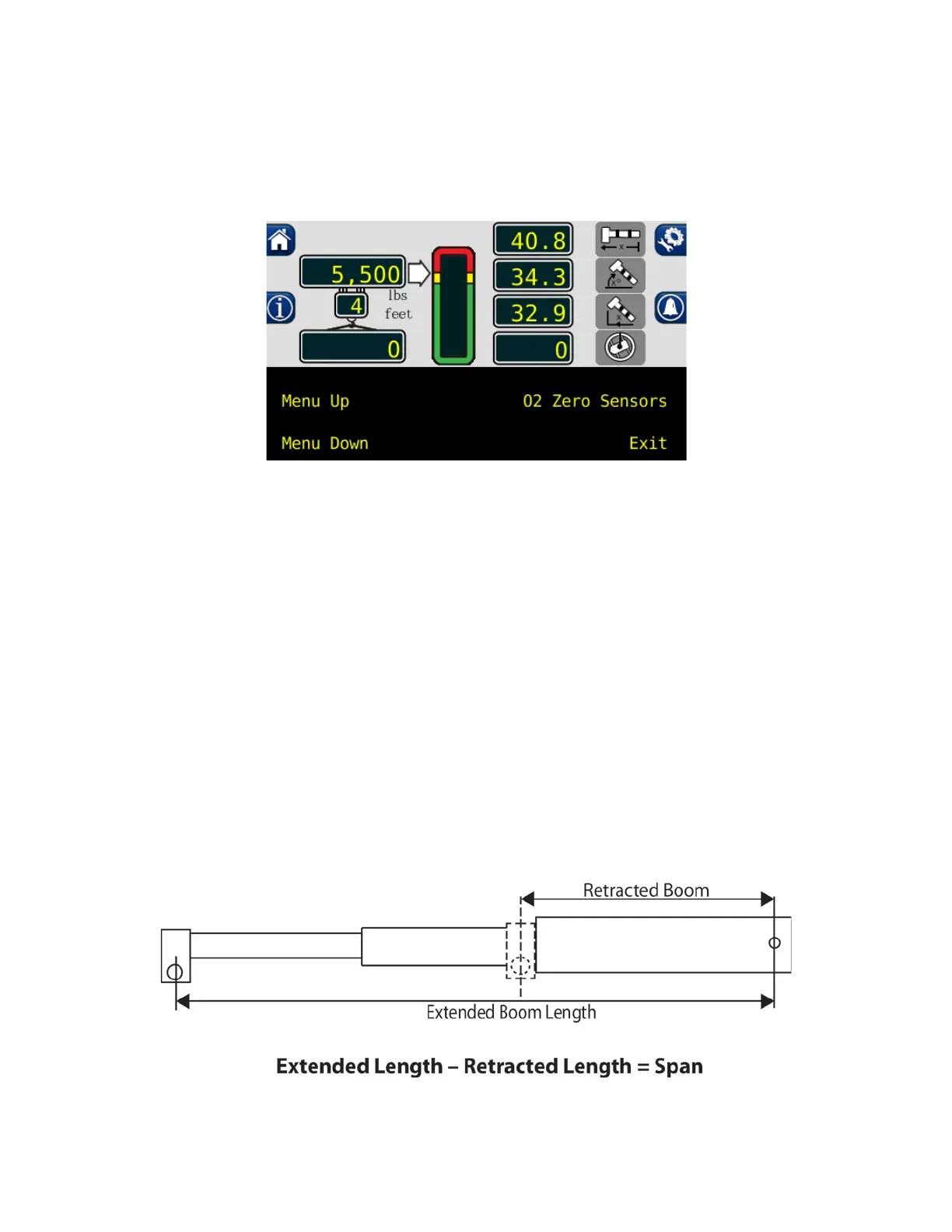
Boom extension and angle readings are dependent on the correct span values to be entered into the
system. These span values are determined by using a digital level on the boom angle, and measuring
the span of boom extension.
 Loading...