-34-
Model G0699 (Mfd. Since 5/15)
56. Slide the crosscut fence against the 90° stop
bolt, then secure it in place by tightening the
M8-1.25 knob with the T-Nut block and 8mm
fender washer on the T-bolt (see Figure 47
on Page 33 and Figure 49 below). Tighten
M8-1.25 knob with 8mm fender washer onto
pivot stud.
Note: Adjusting the crosscut fence in different
positions will be discussed in the Operations
section later in this manual.
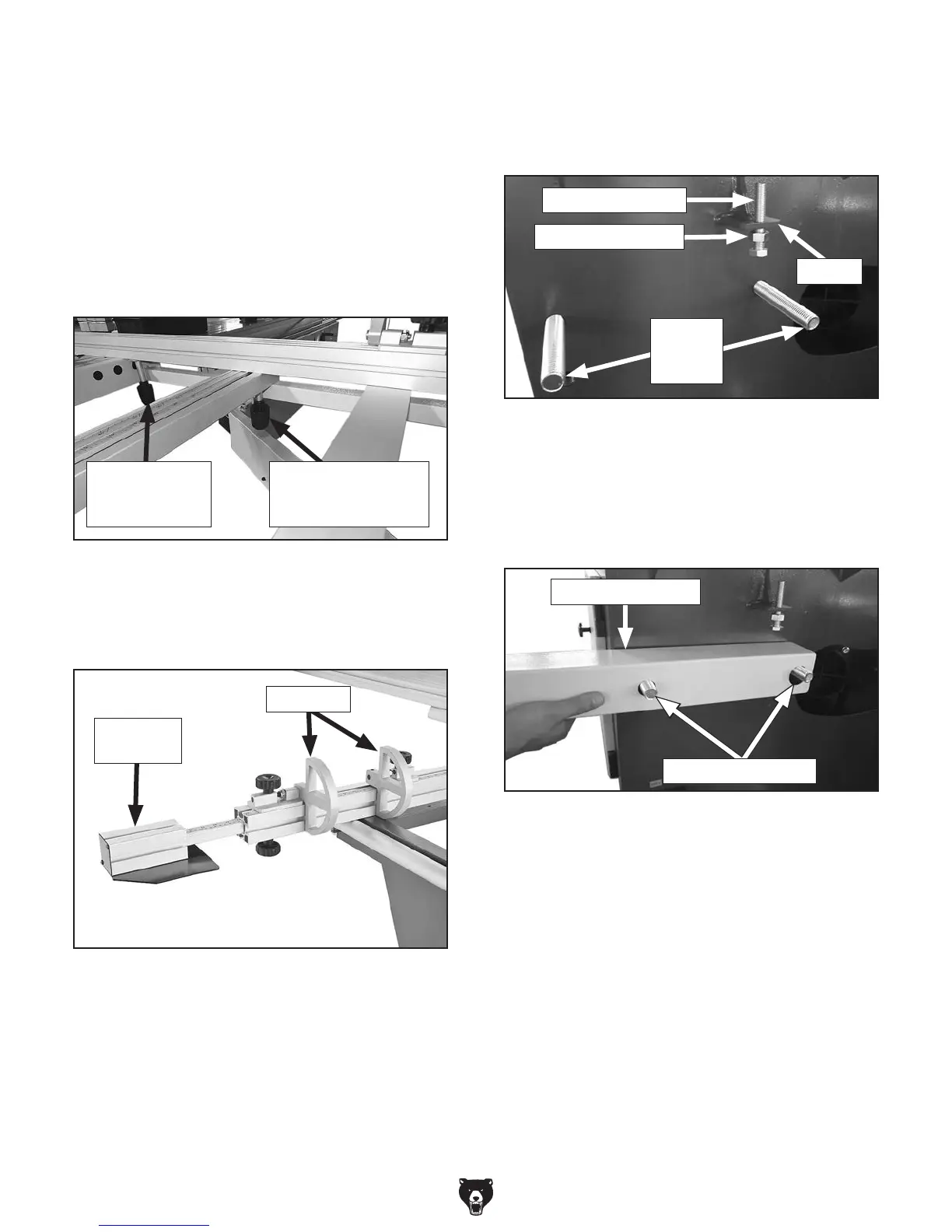
Figure 51. Arm-support studs installed in body
and arm-leveling bolt installed in bracket.
Bracket
Arm-
Support
Studs
Arm-Leveling Bolt
M12-1.75 Jam Nut
58. Thread (1) M12-1.75 x 70 arm-leveling bolt
with M12-1.75 jam nut into bracket con-
nected to rear of machine body, as shown in
Figure 51.
59. Remove hex nuts from pre-installed arm-
support studs (see Figure 51), and install
support-arm base onto arm-support studs, as
shown in Figure 52.
60. Adjust arm-leveling bolt until arm support
base is parallel with floor (see Figure 53 on
Page 35).
Tip: Check this position by using a tape to
measure the distance between each end of
the arm-support base and the floor.
Note: This parallel position helps ensure the
blade guard is parallel with the table once it is
installed. For now, this positioning should be
very close. It will be checked, and if neces-
sary, fine-tuned in a later step.
Figure 52. Installing arm-support base.
Arm-Support Base
Arm-Support Studs
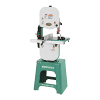
57. Move the crosscut extension fence out so
that you can install the flip stop assemblies,
as shown in Figure 50.
Figure 50. Crosscut flip stops installed.
Flip Stops
Extension
Fence
Figure 49. Crosscut fence secured.
M8-1.25 Knob w/
T-Nut Block & 8mm
Fender Washer
M8-1.25 Knob
w/8mm Fender
Washer
 Loading...