-4-
Model G0842 (Mfd. Since 04/18)
Controls &
Components
Refer to Figures 1–5 and the following descrip-
tions to become familiar with the basic controls of
this machine.
To reduce your risk of
serious injury, read this
entire manual BEFORE
using machine.
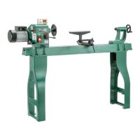
D. Quill: Holds MT#2 centers or tooling. Moves
toward and away from spindle.
E. Quill Locking Nut: Secures quill in position.
F. Tailstock Handwheel: Rotates to move quill
toward and away from spindle.
G. Tailstock Clamp Bolts (2): Secure position
of tailstock along bed.
Figure 2. Tailstock controls.
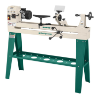
A. ON/OFF Switch w/Disabling Key: Turns
motor ON when flipped up; turns motor OFF
when pressed down. Remove yellow key to
disable switch so motor cannot start.
B. Spindle Speed Lever: Adjusts spindle speed
from low to high within range governed by
pulley belt position (see Page 33 for more
information).
C. Spindle: Accepts MT#2 centers or 1" x 8
TPI (RH) tooling for mounting workpieces.
Rotates counterclockwise (down, toward
front of machine).
Figure 1. Headstock controls.
A
B
C
Headstock
Tailstock
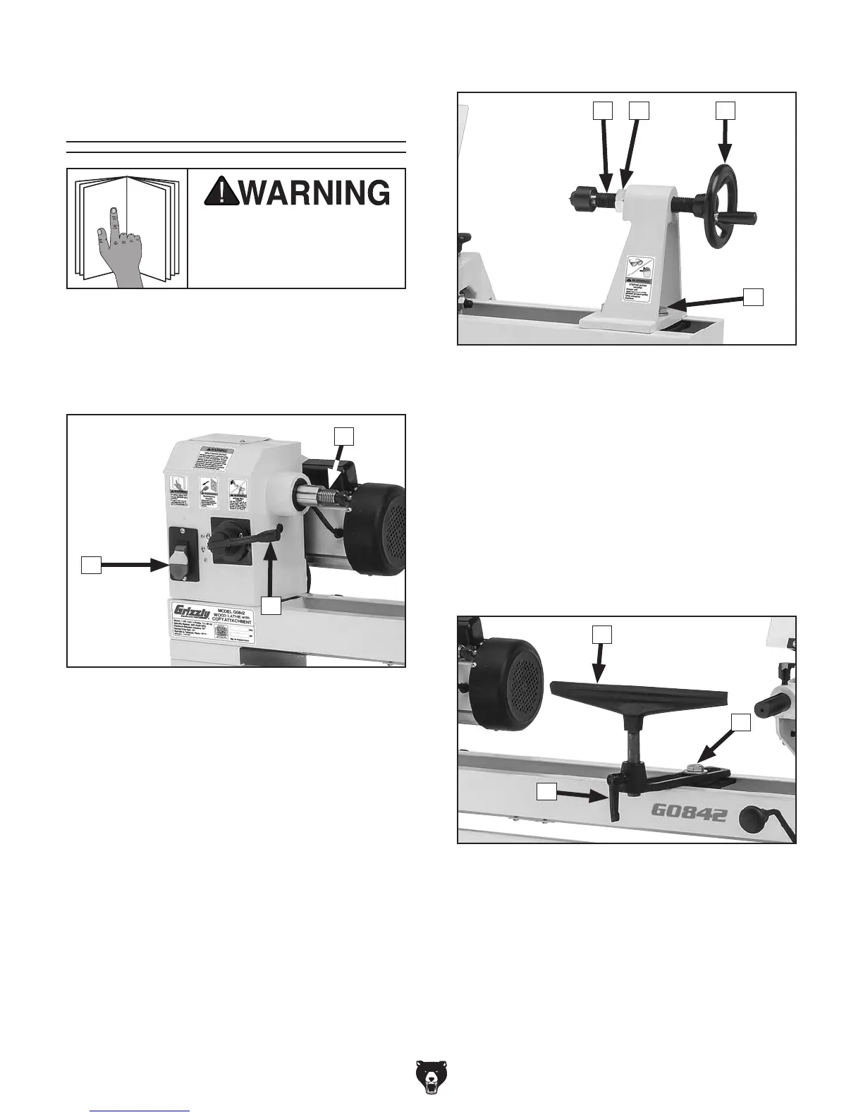
H. Tool Rest: Provides stable platform for cut-
ting tools.
I. Tool Rest Lock Handle: Secures tool rest in
position.
J. Tool Rest Base Locking Bolt: Secures tool
rest base in position along bed.
Figure 3. Tool rest controls.
H
J
I
Tool Rest
FD E
G
 Loading...