-8- G1014Z Combination Sander
Order Of Assembly
SECTION 4: ASSEMBLY
Most of your Combination Sander has been
assembled at the factory. The few remaining
pieces will go together quickly and should be
done in the following order:
1. Stand
2. Mounting Sanding Unit
3. Attaching the Back Stop
4. Attaching Sanding Disc
5. Mounting the Work Table
Note: All die-cut metal parts have a sharp edge
(called “flashing”) on them after they are formed.
This is removed at the factory. Sometimes,
though, a bit of flashing might escape inspection.
Please examine the edges of all die-cut metal
parts before handling them.
TOOLS REQUIRED: Only a few common tools
are required to assemble your Combination
Sander. Specifically, these are: 6" adjustable
wrench, 12mm open end wrench, regular screw-
driver, Phillips screwdriver, and a 4mm Allen
wrench.
Stand
The G1014Z Combination Sander stand is an
open frame style. The four legs are connected
with top and bottom cross braces.
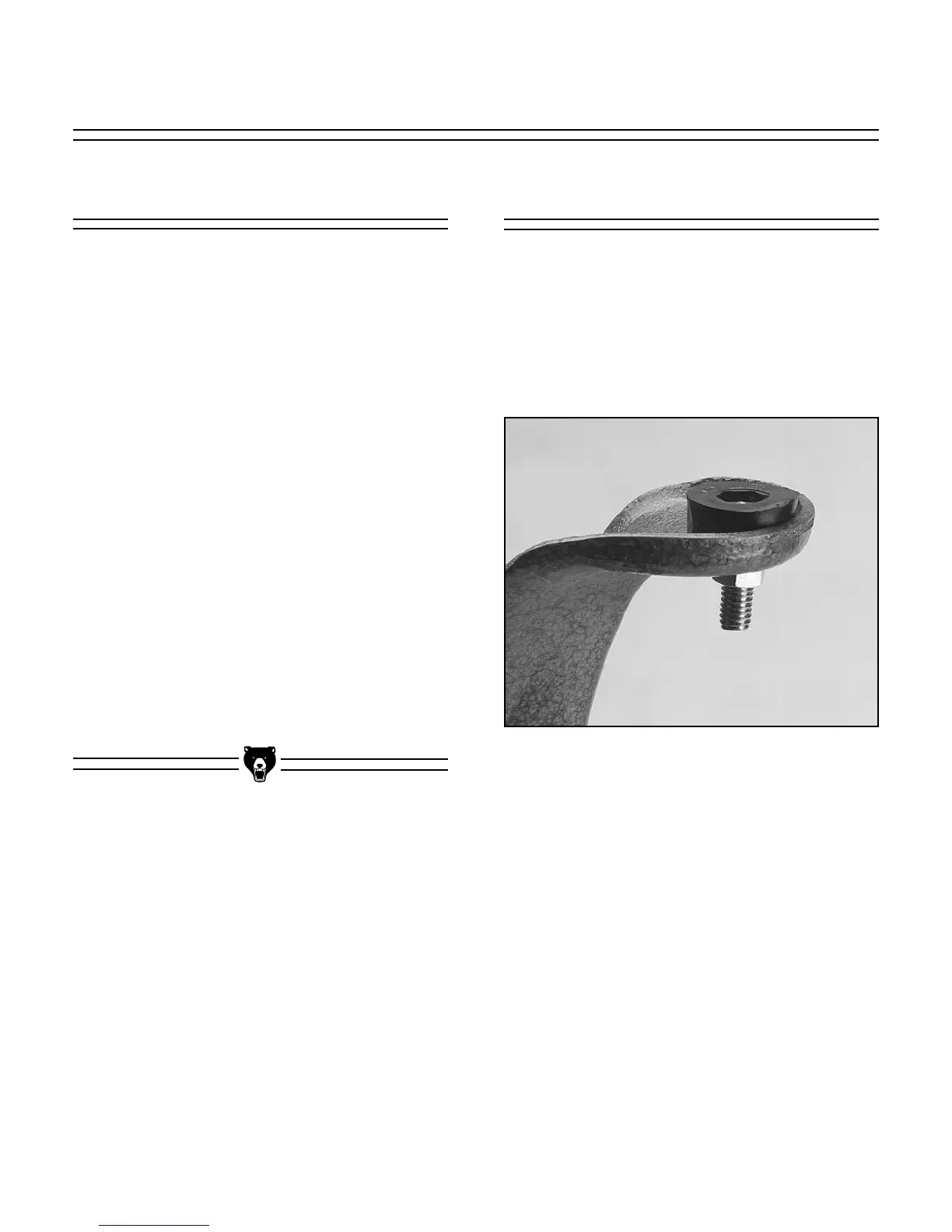
1. Attach Rubber Feet to base using the four
5
⁄16''-18 x 1'' Hex bolts, Hex Nuts and Flat
Washers provided. Figure 2.
Figure 2.

 Loading...