27
28
Chart 5.27
Chart 5.25
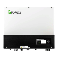
During the actual operation, please pay attention to the installation of current
transformer as the diagram shows below:
Chart 5.26
As illustrated above, open the current transformer and you can see an arrow labeled
on it indicating the direction of current. Put the live wire among the under-detection
wires onto the current transformer. After latching the current transformer, the
installation has been finished.
Notice: the direction (from K to L) of the arrow on the current transformer is
corresponding to the direction of the current in live wire from load to the grid.
Sensor needs to be placed in the power distribution cabinet.
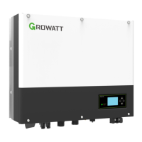
5.4.7 Connection of meter terminal
When customer needs to use meter to monitor the energy flow, the meter terminal
connection steps are as follows:
1.Thread cables through pressure screw, seal ring, threaded sleeve, waterproof
cover.
2.Insert LAN cables into RJ45 terminal, the order of the cables as follow, then press
the RJ45 terminal with suitable tools and make sure all of cables are firmly.
3.Connect pressed RJ45 terminal into corresponding port of the inverter.
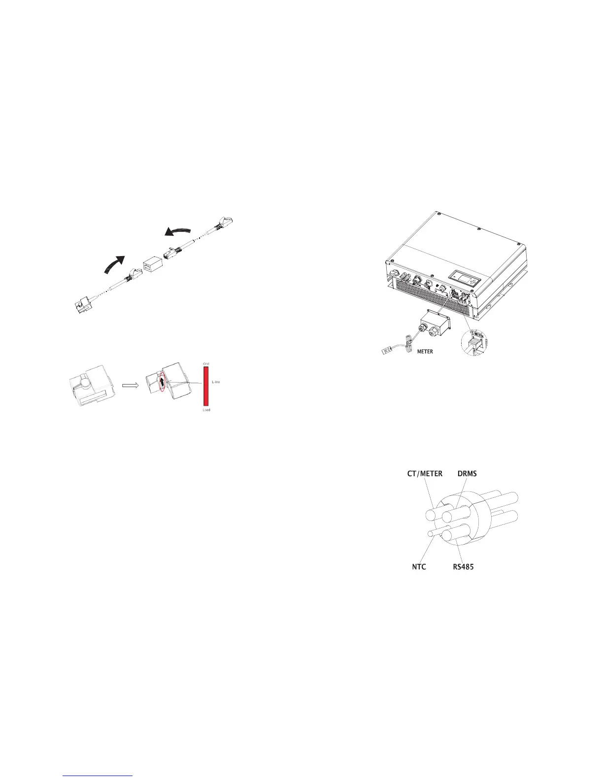
Note:The meter and CT cannot be installed at same time, please set the sensor model
when selecting CT or electricity meter, please refer to section 6.3.3 for details.
5.4.8 Connection of DRMs terminal
When SPH is applied to Australia, the DRMs terminals need to be connected, the
connection way appears as follows:
1. Thread the swivel nut over the “DRMs” cable.
2. Press the cable support sleeve out of the cable gland.
3. Remove the filler plug from the cable support sleeve.
4. Route the “DRMs” cable through an opening in the cable support sleeve.
5. Thread the “DRMs” cable through the cable gland.
6. Insert the RJ45 plug of the network cable into the “DRMs” pin connector on the
inverter until it snaps into place.
Chart 5.28
 Loading...