English (GB)
13
7. Modbus TCP, CIM 500 setup
7.1 Connecting the Ethernet cable
RJ45 plugs and Ethernet cable must be used. The cable shield
must be connected to protective earth at both ends.
The CIM 500 is designed for flexible network installation; the
built-in two port switch makes it possible to daisy chain from
product to product without the need of additional Ethernet
switches. The last product in the chain is only connected to one of
the Ethernet ports. Each Ethernet port has its own MAC address.
Fig. 17 Example of Industrial Ethernet network
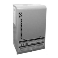
Fig. 18 Example of Ethernet connection
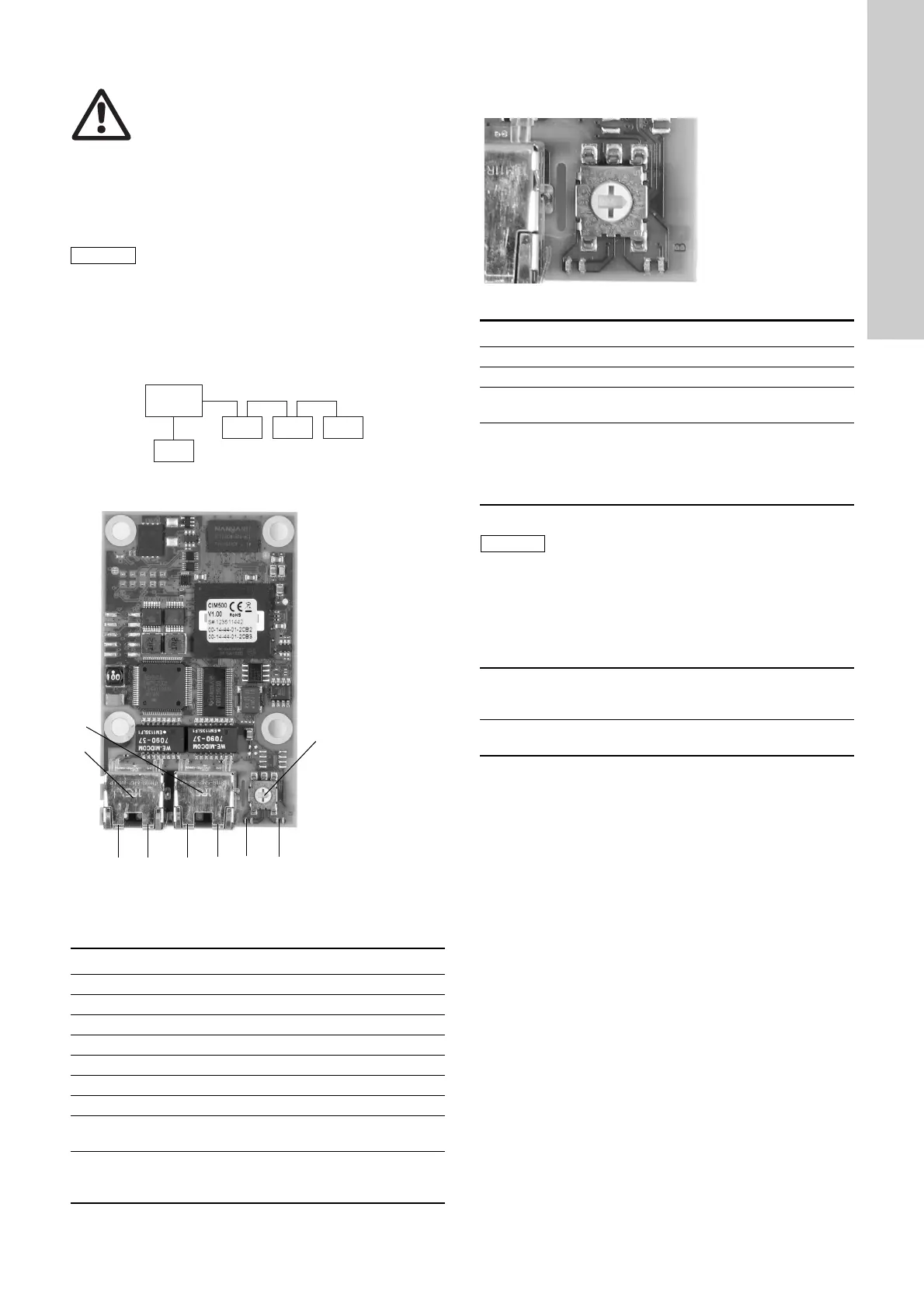
7.2 Setting the Industrial Ethernet protocol
The CIM 500 Ethernet module has a rotary switch for selection of
the Industrial Ethernet protocol. See fig. 19.
Fig. 19 Selecting the Industrial Ethernet protocol
7.3 Setting the IP addresses
The CIM 500 Ethernet module is default set up to a fixed IP
address. It is possible to change the IP address settings from the
built-in web server.
Warning
The CIM 500 must only be connected to SELV or
SELV-E circuits.
It is important to connect cable shield to earth
through earth clamp or to connect cable shield to
earth in the connector.
TM05 6435 4711
TM05 7431 1013
Pos. Description Designation
1 Industrial Ethernet RJ45 Connector 1 ETH1
2 Industrial Ethernet RJ45 Connector 2 ETH2
3 Rotary switch for protocol selection SW1
4 Data activity LED for Connector 1 DATA1
5 Link LED for Connector 1 LINK1
6 Data activity LED for Connector 2 DATA2
7 Link LED for Connector 2 LINK2
8
Green/red status LED for Ethernet
communication
LED 1
9
Green/red status LED for internal
communication between module and
pump.
LED 2
Ethernet
switch
CIM
500
CIM
500
CIM
500
CIM
500
TM05 7431 1013
Pos. Description
0 PROFINET IO (default from factory)
1 Modbus TCP
2..E
Reserved, LED1 will be permanently red to indicate an
invalid configuration
F
Reset to factory default
Note: The rotary switch has to be set in this position for
20 seconds to reset to factory default. During this period
LED1 will be flashing red and green at the same time to
indicate reset will occur.
Every change of the rotary switch setting, when
the module is powered on, will cause the module
to restart.
Default IP settings
used by web server
IP address:192.168.1.100
Subnet mask: 255.255.255.0
Gateway: 192.168.1.1
IP-settings for
Modbus TCP
Must be setup by the Web server
 Loading...