English (GB)
39
14. Fault finding
14.1 Fault finding CIM/CIU 200
Faults in a CIM/CIU 200 can be detected by observing the status
of the two communication LEDs. See the table below and section
3.2 Modbus RTU (CIM 200).
14.1.1 LED status
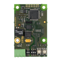
CIM 200 fitted in a Grundfos E-pump
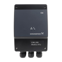
CIM 200 fitted in the CIU 200
Fault (LED status) Possible cause Remedy
1. Both LEDs (LED1 and LED2) remain off
when the power supply is connected.
a) The CIM 200 is fitted incorrectly in the
Grundfos E-pump.
Ensure that the CIM 200 is fitted/connected
correctly.
b) The CIM 200 is defective. Replace the CIM 200.
2. The LED for internal communication
(LED2) is flashing red.
a) No internal communication between the
CIM 200 and the Grundfos E-pump.
Ensure that the CIM 200 is fitted correctly in
the Grundfos E-pump.
3. The LED for internal communication
(LED2) is constantly red.
a) The CIM 200 does not support the
Grundfos E-pump connected.
Contact the nearest Grundfos company.
4. The Modbus LED (LED1) is constantly
red.
a) Fault in the CIM 200 Modbus
configuration.
• Check the transmission speed (switches
SW4 and SW5). If the switches are set to
"software-defined", an invalid value may
have been set via Modbus. Try one of the
preselected transmission speeds, e.g.
19200 bits/s.
• Check that the Modbus address (switches
SW6 and SW7) has a valid value [1-247].
5. The Modbus LED (LED1) is flashing red. a) Fault in the Modbus communication
(fault in parity or cyclic redundancy
check).
• Check the transmission speed (switches
SW4 and SW5).
See section 5.1 Setting the Modbus
transmission speed.
• Check the parity setting (switch SW3).
See section 5.2 Setting the parity.
• Check the cable connection between the
CIM 200 and the Modbus network.
• Check the termination resistor settings
(switches SW1 and SW2).
See section 5.4 Termination resistor.
Fault (LED status) Possible cause Remedy
1. Both LEDs (LED1 and LED2) remain off
when the power supply is connected.
a) The CIU 200 is defective.
Replace the CIU 200.
2. The LED for internal communication
(LED2) is flashing red.
a) No internal communication between the
CIU 200 and the E-pump
• Check the cable connection between the
E-pump and the CIU 200.
• Check that the individual conductors
have been fitted correctly.
• Check the power supply to the E-pump.
3. The LED for internal communication
(LED2) is constantly red.
a) The CIU 200 does not support the
E-pump which is connected.
Contact the nearest Grundfos company.
4. The Modbus LED (LED1) is constantly
red.
a) Fault in the CIM 200 Modbus
configuration.
• Check the transmission speed (switches
SW4 and SW5). If the switches are set to
"software-defined", an invalid value may
have been set via Modbus. Try one of the
preselected transmission speeds, e.g.
19200 bits/s.
• Check that the Modbus address
(switches SW6 and SW7) has a valid
value [1-247].
5. The Modbus LED (LED1) is flashing red. a) Fault in the Modbus communication
(fault in parity or cyclic redundancy
check).
• Check the transmission speed (switches
SW4 and SW5).
See section 5.1 Setting the Modbus
transmission speed.
• Check the parity setting (switch SW3).
See section 5.2 Setting the parity.
• Check the cable connection between the
CIM 200 and the Modbus network.
• Check the termination resistor settings
(switches SW1 and SW2).
See section 5.4 Termination resistor.

 Loading...


