English (GB)
4
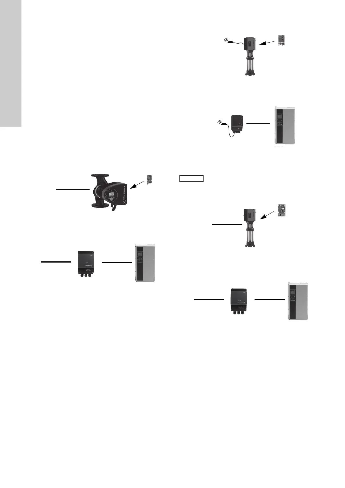
3. System description
3.1 Modbus
The system diagrams provide an overview for the different
technologies of how to connect the CIM/CIU to the Grundfos
E-pump that is to be connected to a Modbus network.
CIM
The CIM solution is an add-on communication module to be
installed internally in a Grundfos E-pump, using a 10-pin
connection. In this setup, the E-pump will supply power to the
CIM. See fig. 1.
For mounting of the CIM add-on module, see the installation and
operating instructions for the E-pump in question.
CIU
The CIU solution is a box with a power supply module and a CIM
Modbus module. It can either be mounted on a DIN rail or on a
wall.
It is used in conjunction with Grundfos E-pumps that do not
support an internal, add-on communication module (CIM).
See fig. 2.
3.2 Modbus RTU (CIM 200)
Fig. 1 Principle sketch of CIM 200 Modbus RTU solution with
add-on CIM module installed inside the pump.
The figure shows a MAGNA3 pump.
Fig. 2 Principle sketch of CIU 200 Modbus RTU solution.
The gfigure shows a CUE-drive for pumps.
The Grundfos CIM/CIU is connected as a Modbus slave directly
to the Modbus network.
3.3 Modbus GSM/GPRS (CIM 250)
Fig. 3 Principle sketch of CIM 250 Modbus GSM/GPRS
solution with internal add-on CIM module and external
antenna. The figure shows a CRE pump.
Fig. 4 Principle sketch of CIU 250 Modbus GSM/GPRS
solution with external antenna. The figure shows a
CUE-drive for pumps.
3.4 Modbus TCP (CIM 500)
Fig. 5 Principle sketch of CIM 500 Modbus TCP solution with
internal add-on CIM module. The figure shows a CRE
pump.
Fig. 6 Principle sketch of CIU 500 Modbus TCP solution.
The figure shows a CUE drive for pumps.
TM04 2295 2208TM05 74391013
Modbus RTU
GENIbus
RS485
CIU 200
TM04 9232 3610TM04 9233 3610
3G/4G are not supported via CIM 250.
TM05 7431 1013TM05 7452 1013
GENIbus
RS-485
CIU 250
GSM/GPRS
Modbus TCP
GENIbus
RS485
CIU 500
 Loading...