5.2 Setting the stop bits and the parity bit
When software-defined transmission speed is enabled
(SW4 and SW5 are ON), software-defined parity and stop
bits are also enabled.
You can set the parity either manually by using SW3 or via
software-defined settings.
Manual setting of parity
Default byte format (11 bits):
• 1 start bit
• 8 data bits (least significant bit sent first)
• 1 parity bit (even parity)
• 1 stop bit.
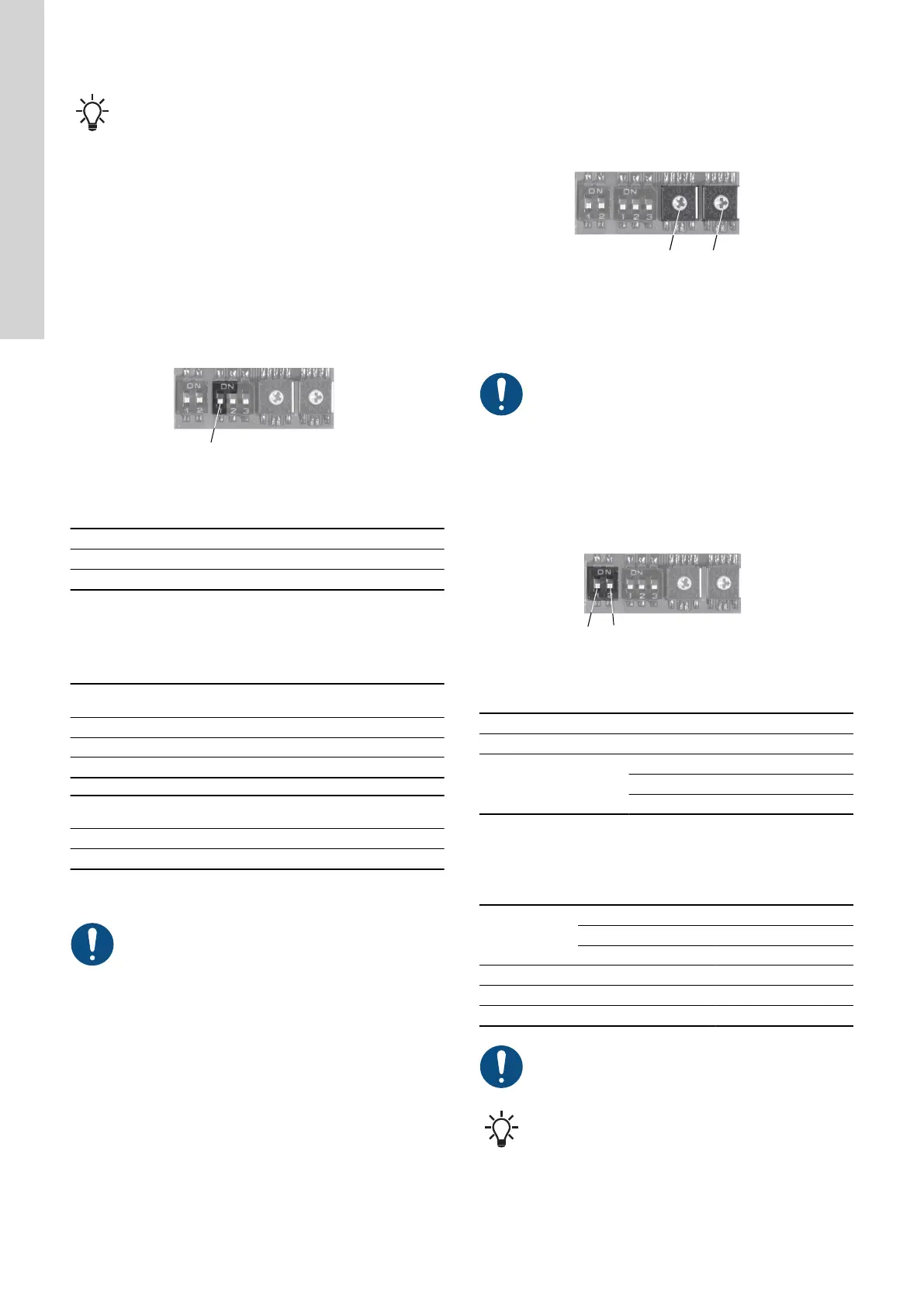
The default setting of the CIM 200 Modbus module is even parity (1
stop bit). It is possible to change the parity using DIP switch SW3.
You can change the parity to no parity (2 stop bits).
TM041709
Parity
DIP switch settings
Parity
SW3
Even parity, 1 stop bit OFF
No parity, 2 stop bits ON
Software-defined parity and stop bits
When SW4 and SW5 are set to "software-defined", the value in the
holding registers at addresses 00009 and 00010 will override the
setting of SW3.
Software-defined parity
Value to set in register
00009
No parity [default] 0
Even parity 1
Odd parity 2
Software-defined stop bit
Value to set in register
00010
1 stop bit [default] 1
2 stop bits 2
The software-defined parity and stop bit values are stored in the
communication interface and remain after a power-off.
For software-defined parity and stop bits to become
active, you must set SW4 and SW5 to ON.
Related information
5.1 Setting the Modbus transmission speed
5.3
Modbus address selection
A Modbus slave on a Modbus network must have a unique address
from 1-247. Address 0 is reserved for broadcasting, and is not a
valid slave address.
To set the Modbus address, use two hexadecimal rotary switches
(SW6 and SW7).
TM041706
Setting the Modbus address
For a complete overview of Modbus addresses, see
section Modbus RTU rotary switch addresses.
When software-defined transmission speed is enabled,
software-defined address is also enabled and you set the
address via register 00003.
You must set the Modbus address decimally from 1 to
247.
5.4 Termination resistor
The termination resistor is fitted on CIM 200 Modbus and has an
effective value of 120 Ω.
CIM 200 has a DIP switch with two switches, SW1 and SW2, for
cutting the termination resistor in and out.
TM041701
Cutting the termination resistor in and out
DIP switch settings
Status
SW1 SW2
Cut in ON ON
Cut out
OFF OFF
ON OFF
OFF ON
Default setting: Termination resistor cut out.
Cable length
We recommend the following maximum lengths:
Bit/s
Maximum cable length
Terminated cable Unterminated cable
[m/ft] [m/ft]
1200-9600 1200/4000 1200/4000
19200 1200/4000 500/1700
38400 1200/4000 250/800
To ensure a stable and reliable communication, it is
important that only the termination resistor of the first and
last units in the Modbus network are cut in.
All switch settings will be effective immediately after
setting the values. No power-off is needed.
10
English (GB)
 Loading...