6.2 Status LEDs
The CIM 260 module has two LEDs.
• Yellow and green status LED1 for cellular communication.
• Red and green status LED2 for internal communication between
CIM 260 and the Grundfos product.
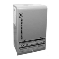
LED1, yellow and green
TM083816
LED1 status
Pos. Status Description
1 Flashing yellow Searching for cellular network.
2
Pulsating yellow, single
pulse
Connection to the cellular network
has been established.
3
Pulsating green, single
pulse
Communication via data connection.
4 Green, 3 seconds
Sending or receiving an SMS
message.
LED2, red and green
Status
Description
Off CIM 260 has been switched off.
Flashing red
No communication between CIM 260 and the
Grundfos product.
Permanently red
CIM 260 does not support the connected version of
the Grundfos product.
Permanently green
The connection between CIM 260 and the Grundfos
product is OK.
7. CIM 500 Modbus TCP setup
WARNING
Electric shock
Death or serious personal injury
‐ Connect CIM 500 only to SELV circuits.
7.1 Connecting the Ethernet cable
Use RJ45 plugs and Ethernet cable. Connect the cable shield to
protective earth at both ends.
It is important to connect the cable shield to earth through
an earth clamp or to connect the cable shield to earth in
the connector.
CIM 500 is designed for flexible network installation; the built-in two
port switch makes it possible to daisy chain from product to product
without the need for additional Ethernet switches. The last product
in the chain is only connected to one of the Ethernet ports. Each
Ethernet port has its own MAC address.
Ethernet
switch
CIM
500
CIM
500
CIM
500
CIM
500
TM083815
Example of Industrial Ethernet network
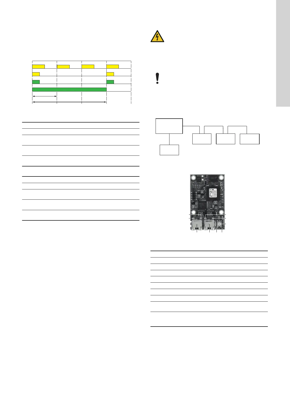
TM079842
Example of Ethernet connection
Pos. Description Designation
1 Industrial Ethernet RJ45 connector 1 ETH1
2 Industrial Ethernet RJ45 connector 2 ETH2
3 Rotary switch for protocol selection SW1
4 Data activity LED for connector 1 DATA1
5 Link LED for connector 1 LINK1
6 Data activity LED for connector 2 DATA2
7 Link LED for connector 2 LINK2
8
Green and red status LED for Ethernet
communication
LED1
9
Green and red status LED for internal
communication between the module and the
product.
LED2
13
English (GB)
 Loading...