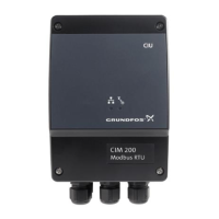
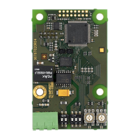
English (GB) Functional profile and user manual
Original functional profile and user manual
Table of contents
1. General information ........................4
1.1 Hazard statements..........................4
1.2 Notes ..................................5
2. Introduction .............................5
2.1 About this functional profile.....................5
2.2 Assumptions .............................5
2.3 Definitions and abbreviations ...................5
3. System description ........................6
3.1 Modbus ................................6
3.2 CIM 200 Modbus RTU .......................6
3.3 CIM 260 3G/4G cellular Modbus .................6
3.4 CIM 500 Modbus TCP........................6
4. Specifications ............................7
4.1 CIM module ..............................7
4.2 CIM 200 Modbus RTU .......................7
4.3 CIM 260 3G/4G cellular .......................8
4.4 CIM 500 Modbus TCP........................8
5. CIM 200 Modbus RTU setup ...................9
5.1 Setting the Modbus transmission speed .............9
5.2 Setting the stop bits and the parity bit .............10
5.3 Modbus address selection ....................10
5.4 Termination resistor ........................10
5.5 Status LEDs.............................11
6. CIM 260 3G/4G cellular Modbus setup ...........11
6.1 Installation ..............................11
6.2 Status LEDs.............................13
7. CIM 500 Modbus TCP setup ..................13
7.1 Connecting the Ethernet cable..................13
7.2 Setting the Industrial Ethernet protocol ............14
7.3 Setting the IP addresses .....................14
7.4 Establish a connection to the webserver............14
7.5 Status LEDs.............................14
7.6 DATA and LINK LEDs .......................15
8. Modbus function code overview ...............15
9. Modbus register addresses ..................16
9.1 Register block overview......................16
9.2 CIM configuration register block.................16
9.3 CIM status register block .....................18
9.4 Cellular network Real Time Clock................19
9.5 Pump control register block ...................20
9.6 Pump status register block ....................22
9.7 Pump data register block .....................25
9.8 Sensor-dependent measurements ...............27
9.9 Alarm simulation register block (not CUE)...........28
9.10 User register block .........................28
10. Detailed descriptions of registers ..............29
10.1 Control mode ............................29
10.2 Setpoint in closed-loop control..................30
10.3 Setpoint in open-loop control...................30
10.4 Alarms and warnings .......................31
11. Modbus RTU commissioning, step-by-step guides . ..32
11.1 Hardware setup, CIM 200 ....................32
11.2 Hardware setup, CIU 200.....................32
11.3 Hardware setup, CIM 260 data connection ..........32
11.4 Hardware setup, CIU 260 data connection ..........33
11.5 CIM 500 Modbus TCP communication setup .........33
11.6 CIU 500 Modbus TCP communication setup .........34
12. Detailed descriptions of functionality ............34
12.1 APN..................................34
13. Modbus RTU telegram examples ...............37
13.1 Modbus telegram overview....................37
13.2 Read holding registers, 0x03...................37
13.3 Read input registers, 0x04 ....................38
13.4 Write single register, 0x06 ....................38
13.5 Write multiple registers, 0x10 ..................38
13.6 Diagnostics, 0x08 .........................39
13.7 Diagnostics register interpretation ...............39
13.8 Diagnostics: return query data..................39
13.9 Reading the CIM configuration register block.........40
13.10 Setting the setpoint ........................40
13.11 Setting the control mode .....................40
13.12 Starting the E-pump ........................41
13.13 Stopping the E-pump .......................41
14. Fault finding the product ....................42
14.1 CIM 200 ...............................42
14.2 CIM/CIU 260 ............................44
14.3 CIM 500 ...............................46
15. Modbus RTU rotary switch addresses ...........48
16. Disposing of the product ....................49
17. Grundfos alarm and warning codes .............50
1. General information
Read this document before you install the product.
Installation and operation must comply with local
regulations and accepted codes of good practice.
1.1 Hazard statements
The symbols and hazard statements below may appear in Grundfos
installation and operating instructions, safety instructions and
service instructions.
DANGER
Indicates a hazardous situation which, if not avoided, will
result in death or serious personal injury.
WARNING
Indicates a hazardous situation which, if not avoided,
could result in death or serious personal injury.
CAUTION
Indicates a hazardous situation which, if not avoided,
could result in minor or moderate personal injury.
The hazard statements are structured in the following way:
SIGNAL WORD
Description of the hazard
Consequence of ignoring the warning
• Action to avoid the hazard.
4
English (GB)

 Loading...


