English (GB)
6
4.3 Electrical connection
The electrical connection should be carried out by an
authorised electrician in accordance with local
regulations.
4.3.1 Connection of power supply and GENIbus
1. Remove the cover.
2. Connect the supply cable to the CIU unit
(fig. 4, pos. 1, 2 and 3).
3. Loosen the earth clamp (fig. 5, pos. 4).
4. Connect the conductors to terminals A, Y and B
(fig. 5, pos. 1, 2 and 3).
5. Connect the cable screen under the earth clamp,
and tighten the earth clamp (fig. 5, pos. 4).
6. Connect the network cable to the CIM module.
See the installation and operating instructions for
the CIM module in question.
7. Fit the cover.
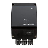
Fig. 4 Electrical connection and earthing
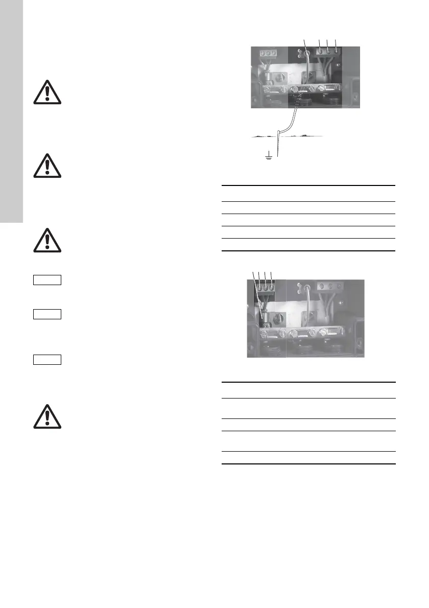
Fig. 5 GENIbus connection
Warning
Before beginning the electrical connection,
make sure that the electricity supply has
been switched off and that it cannot be
accidentally switched on.
Warning
Applies to supply voltages above 30 V
RMS
/ 60 VDC:
The installation must incorporate a circuit
breaker in order to switch off the mains
supply. It must be close to the CIU unit and
easily accessible for the operator. It must
be marked as circuit breaker for the CIU
unit. The circuit breaker must be according
to IEC 60947-1 and IEC 60947-3.
Warning
Branch circuit protection:
The CIU unit must be protected by a
branch circuit fuse in accordance with
local and national regulations.
Supply voltage to the CIU unit:
24-240 VAC/VDC - 10 %/+ 15 %.
If the CIU unit is mounted on a DIN rail
WITHOUT earth connection or on a wall, it
must be connected to earth via the earth
terminal. See fig. 4, pos. 4.
To ensure a stable and reliable
communication, the cable screen for
GENIbus connection must always be
connected to the earth clamp.
See fig. 5, pos. 4.
Warning
The CIU unit and GENIbus must only be
connected to SELV or SELV-E circuits.
TM04 1985 1608
Pos. Description
1 Protective earth terminal
2 Neutral terminal
3 Phase terminal
4 Earth terminal
TM04 1730 1008
Pos. Designation Description
1A
GENIbus terminal A
(positive data signal)
2 Y GENIbus terminal Y
3B
GENIbus terminal B
(negative data signal)
4 - Earth clamp