21
English (US)
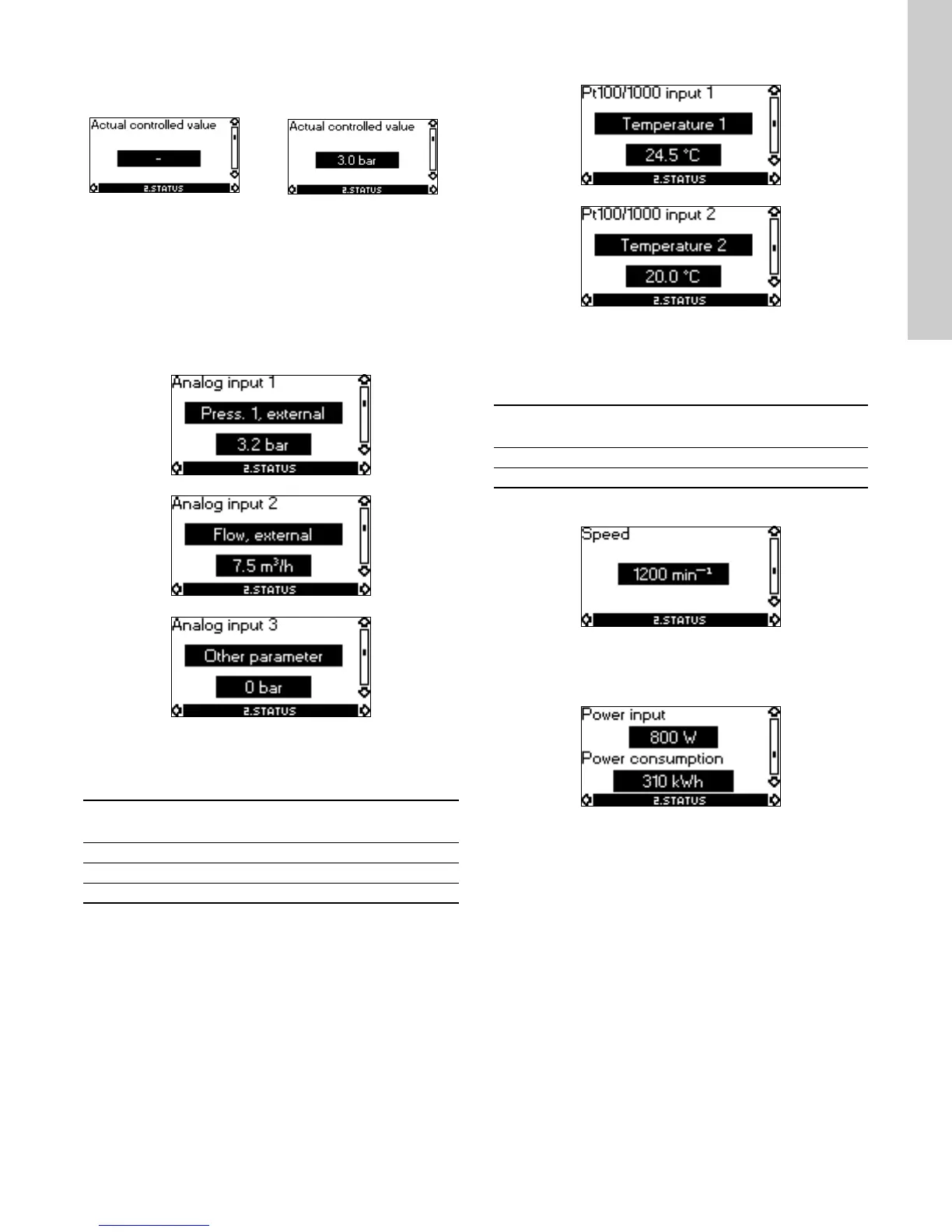
Actual controlled value
The actual controlled value will appear in this display if a sensor
has been connected and the function of the analog input has
been set to "Feedback sensor".
If two separate sensors are used to measure a differential
parameter, the function of two analog inputs must be set to
"Feedback sensor". The actual controlled value will be the
absolute difference between the two sensor measurements. See
section Analog input 1, 2 and 3, Function, page 28.
Analog input 1, 2 and 3
These displays show the measured parameter and the
corresponding value.
The number of available displays depends on the pump type. See
below.
Pt100/1000 input 1 and 2
These displays show the measured parameter and the
corresponding value. The measured temperatures will appear in
these displays if Pt100 or Pt1000 sensors have been connected.
The number of available displays depends on the pump type. See
below.
Speed
Tolerance: ± 5 %.
This display shows the actual speed.
Power input and power consumption
Tolerance: ± 10 %.
• "Power input" indicates the actual power consumption.
• "Power consumption" indicates an accumulated value which
cannot be reset.
Without sensor With pressure sensor
Function (terminal) CME
CRE, CRIE, CRNE, SPKE,
MTRE
Analog input 1 (4) ●●
Analog input 2 (7) ●●
Analog input 3 (14) - ●
Function (terminal) CME
CRE, CRIE, CRNE,
SPKE, MTRE
Pt100/1000 input 1 (17) - ●
Pt100/1000 input 2 (19) - ●
 Loading...


