10
6. Installing the pump
6.1 Pump location
The pump should be located in a dry, well-ventilated area which is
not subject to freezing or extreme variation in temperature.
Care must be taken to ensure the pump is mounted at least
6 inches (150 mm) clear of any obstruction or hot surfaces.
The motor requires an adequate air supply to prevent overheating
and adequate vertical space to remove the motor for repair.
For open systems requiring suction lift the pump should be
located as close to the water source as possible to reduce piping
losses.
6.2 Foundation
Concrete or similar foundation material should be used to provide
a secure, stable mounting base for the pump.
See table of bolt hole center line dimensions for the various pump
types.
Secure the pump to the foundation using all four bolts and shim
pump base to assure the pump is vertical and all four pads on the
base are properly supported (uneven surfaces can result in pump
base breakage when mounting bolts are tightened).
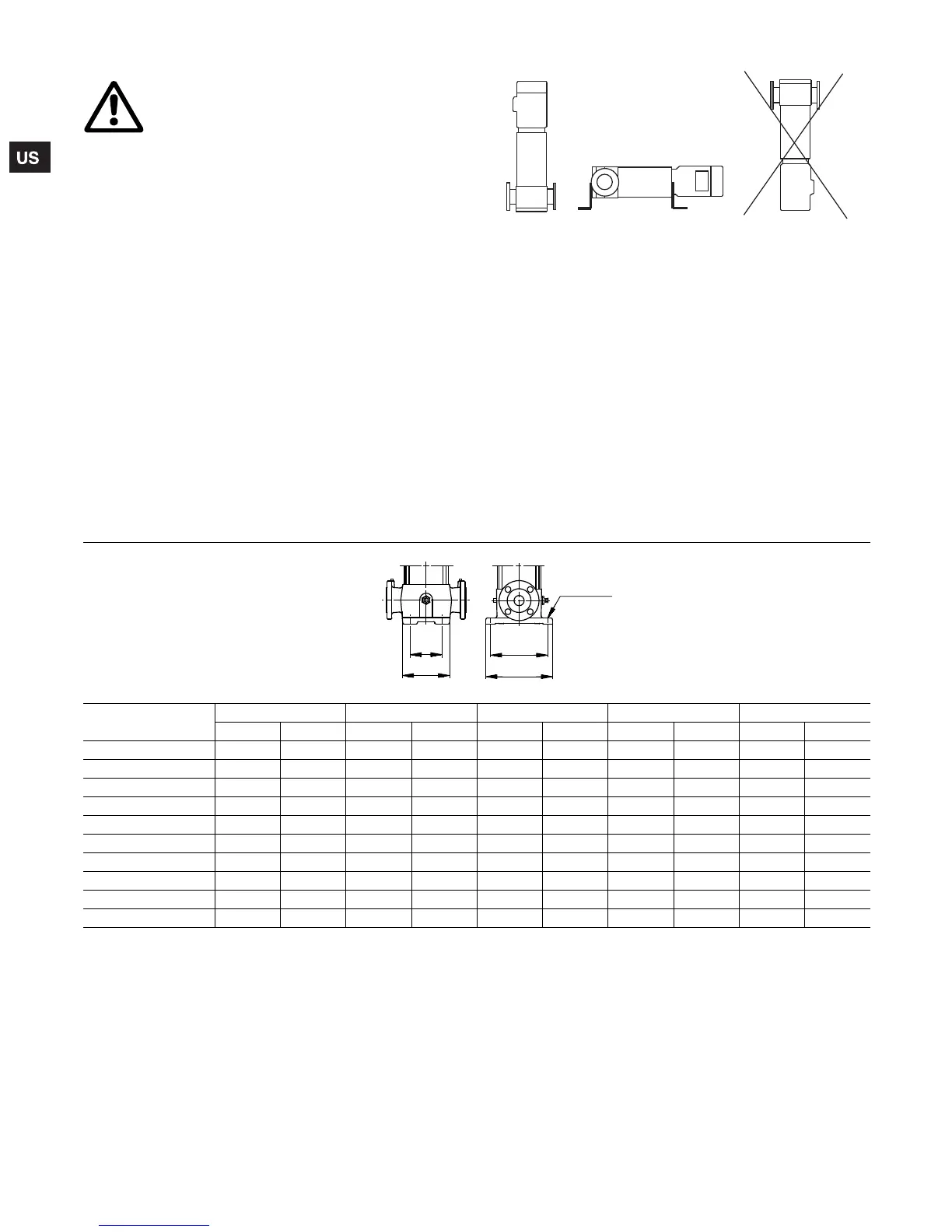
Fig. 4 Pump position
The pump can be installed vertically or horizontally; see fig. 4.
Ensure that an adequate supply of cool air reaches the motor
cooling fan. The motor must never fall below the horizontal plane.
Arrows on the pump base show the direction of flow of liquid
through the pump.
To minimize possible noise from the pump, it is advisable to fit
expansion joints on either side of the pump and anti-vibration
mountings between the foundation and the pump.
Note: Care should be taken to ensure that the vent plug is
located in the uppermost position.
Isolating valves should be fitted either side of the pump to avoid
draining the system if the pump needs to be cleaned, repaired or
replaced.
Warning
Do not energize pump until properly installed.
TM04 3906 0409
TM00 2256
Pump type
L1 L2 B1 B2 ø
in mm in mm in mm in mm in mm
CR 1s, 1, 3, 5 3 15/16 100 5 11/16 145 7 1/16 180 8 11/16 220 1/2 13
CRI, CRN 1s 1, 3, 5
3 15/16 100 5 7/8 150 7 1/16 180 8 11/16 220 1/2 13
CR 10, 15, 20 5 1/8 130 6 15/16 176 8 7/16 215 10 1/16 256 9/16 13.5
CRN 10, 15, 20
5 1/8 130 7 7/8 200 8 7/16 215 9 3/4 248 1/2 13
CR 32 6 11/16 170 8 3/4 223 9 7/16 240 11 3/4 298 9/16 14
CRN 32 6 11/16 170 8 7/8 226 9 7/16 240 11 3/4 298 9/16 14
CR 45,64 7 1/2 190 9 3/4 248 10 1/2 266 13 1/16 331 9/16 14
CRN 45,64 7 1/2 190 9 7/8 251 10 1/2 266 13 1/16 331 9/16 14
CR(N) 90 7 13/16 199 10 1/4 261 11 280 13 11/16 348 9/16 14
CR(N) 120, 150 10 13/16 275 13 9/16 344 14 15/16 380 18 9/16 472 11/16 18
Grundfos.bk Page 10 Wednesday, March 18, 2009 10:38 AM

 Loading...