13
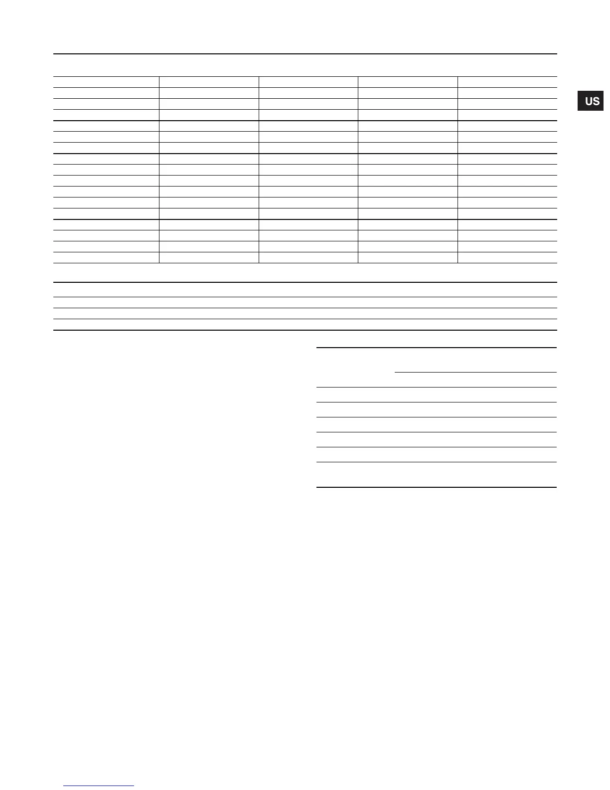
6.9 Minimum continuous duty flow rates
* Grundfos Cool-Top® is only available in the following pump types.
6.10 Check valves
A check valve may be required on the discharge side of the pump
to prevent the pump’s inlet pressure from being exceeded.
For example, if a pump with no check valve is stopped because
there is no demand on the system (all valves are closed), the high
system pressure on the discharge side of the pump will “find” its
way back to the inlet of the pump.
If the system pressure is greater than the pump’s maximum inlet
pressure rating, the limits of the pump will be exceeded and a
check valve needs to be fitted on the discharge side of the pump
to prevent this condition. This is especially critical for CRN-SF
applications because of the very high discharge pressures
involved. As a result, most CRN-SF installations require a check
valve on the discharge piping.
6.11 Temperature rise
It may sometimes be necessary to stop the flow through a pump
during operation.
At shut-off, the power to the pump is transferred to the pumped
liquid as head, causing a temperature rise in the liquid.
The result is risk of excess heating of and consequent damage to
the pump. The risk depends on the temperature of the pumped
liquid and for how long the pump is operating without flow; see
the following temperature rise chart.
6.12 Conditions/Reservations
The listed times are subject to the following conditions/
reservations:
• No exchange of heat with the surrounding.
• The pumped liquid is water with a specific heat of 1.0
Btu
/
lb.
°F
(4.18
kJ
/
kg
°C).
• Pump parts (chambers, impellers and shaft) have the same
thermal capacity as water.
• The water in the base and the pump head is not included.
These reservations should give sufficient safety margin against
excessive temperature rise.
The maximum temperature must not exceed the pump maximum
rating.
Pump Type
min °F to 176 °F
(min °C to 80 °C)
at 210°F
(at 99°C)
at 248°F
(at 120°C)
at 356°F
(at 180°C)
CR, CRI, CRN 1s 0.5 0.7 1.2 1.2*
CR, CRI, CRN 1 0.9 1.3 2.3 2.3*
CR, CRI, CRN 3 1.6 2.4 4.0 4.0*
CR, CRI, CRN 5 3.0 4.5 7.5 7.5*
CR, CRI, CRN 10 5.5 8.3 14 14*
CR, CRI, CRN 15 9.5 14 24 24*
CR, CRI, CRN 20 11 17 28 28*
CR, CRN 32 14 21 35 35*
CR, CRN 45 22 33 55 55*
CR, CRN 64 34 51 85 85*
CR, CRN 90 44 66 110 110*
CR, CRN 120 60 90 N/A N/A
CR, CRN 150 75 115 N/A N/A
CRT 2 1.3 2.0 3.3 N/A
CRT 4 3.0 4.5 7.5 N/A
CRT 8 4.0 6.0 10 N/A
CRT 16 8.0 0.7 20 N/A
Pump Type CR 1s CR 1 CR 3 CR 5 CR 10 CR 15 CR 20 CR 32 CR 45 CR 64 CR 90
Standard (CR) ••••
I Version (CRI) •••••••
N Version (CRN) •••••••••••
Pump type
Time for temperature rise
of 18 °F (10 °C)
Seconds Minutes
CR 1s, 1, 3 210 3.5
CR 5 240 4.0
CR 10 210 3.5
CR 15 150 2.5
CR 20 120 2.0
CR 32, 45, 64, 90,
120, 150
60 1.0
Grundfos.bk Page 13 Wednesday, March 18, 2009 10:38 AM

 Loading...