14
6.13 Electrical
6.14 Motor
Grundfos CR pumps are supplied with heavy-duty 2-pole (3600
rpm nominal), ODP or TEFC, NEMA C frame motors selected to
our rigid specifications.
Motors with other enclosure types and for other voltages and
frequencies are available on a special-order basis.
CRN-SF pumps are supplied with an IEC (metric) type motor with
a reverse thrust bearing.
If you are replacing the pumping unit, but are using a motor
previously used on another CR pump, be sure to read
10. Replacing the motor for proper adjustment of the coupling
height.
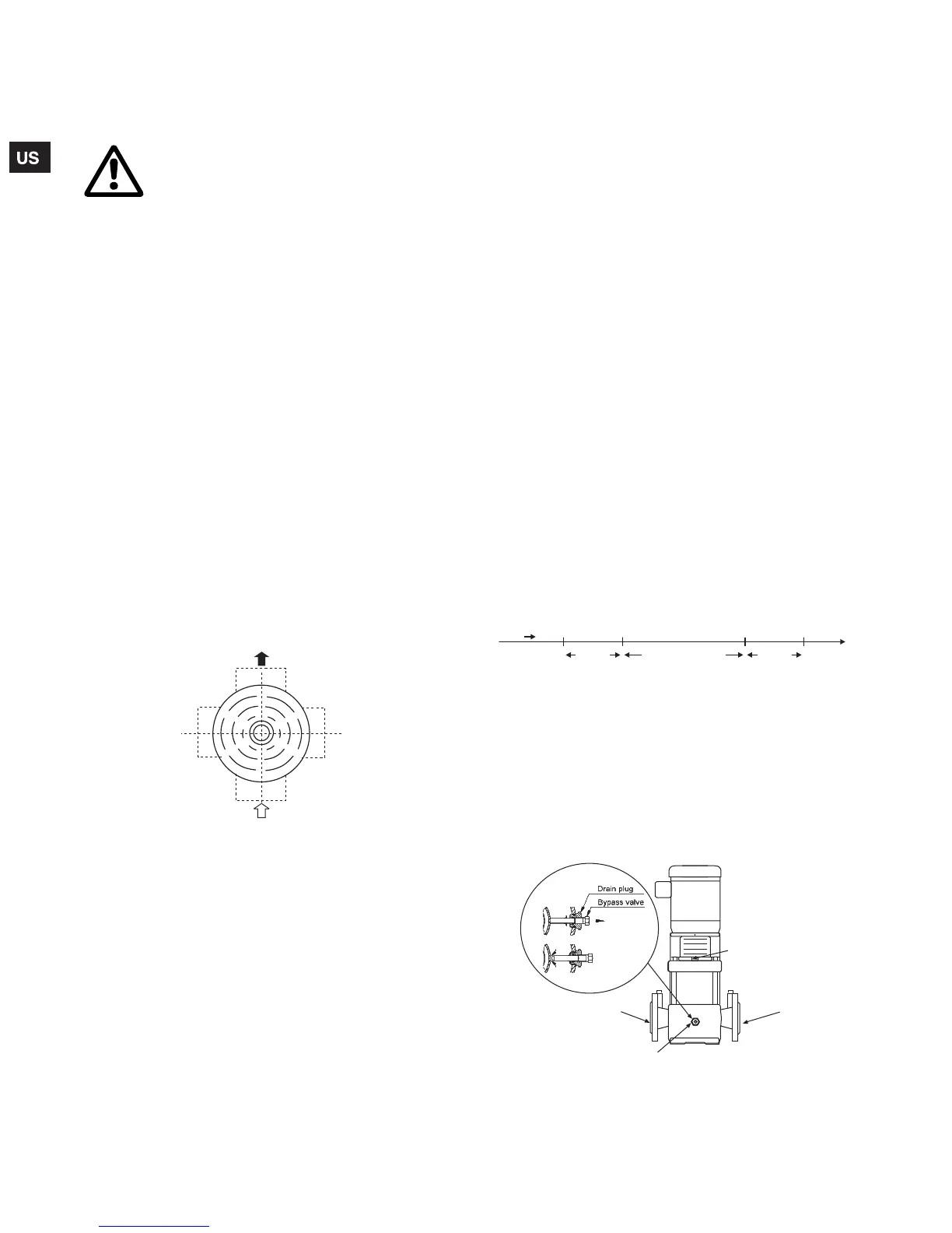
6.15 Position of Terminal Box
The motor terminal box can be turned to any of four positions in
steps of 90°.
To rotate the terminal box, remove the four bolts securing the
motor to the pump but do not remove the shaft coupling. Turn the
motor to the desired location; replace and securely tighten the
four bolts; see fig. 11.
Fig. 11 Motor terminal box positions (top view)
6.16 Field Wiring
Wire sizes should be based on the current carrying properties of
a conductor as required by the latest edition of the National
Electrical Code or local regulations. Direct on line (D.O.L.)
starting is approved due to the extremely fast run-up time of the
motor and the low moment of inertia of the pump and motor. If
D.O.L. starting is not acceptable and reduced starting current is
required, an auto transformer, resistant starter or soft start should
be used. It is suggested that a fused disconnect be used for each
pump where service and standby pumps are installed.
6.17 Motor protection
6.17.1 Single-Phase Motors
With the exception of 10 HP motors which require external
protection, single-phase CR pumps are equipped with multi-
voltage, squirrel-cage induction motors with built-in thermal
protection.
6.17.2 Three-Phase Motors
CR pumps with three-phase motors must be used with the proper
size and type of motor-starter to ensure the motor is protected
against damage from low voltage, phase failure, current
imbalance and overloads.
A properly sized starter with manual reset and ambient-
compensated extra quick trip in all three legs should be used. The
overload should be sized and adjusted to the full-load current
rating of the motor. Under no circumstances should the overloads
be set to a higher value than the full load current shown on the
motor nameplate. This will void the warranty.
Overloads for auto transformers and resistant starters should be
sized in accordance with the recommendations of the
manufacturer.
Three phase MLE motors (CRE-Pumps) require only fuses as a
circuit breaker. They do not require a motor starter. Check for
phase imbalance (worksheet is provided; see p. 23).
Note: Standard allowable phase imbalance difference is 5%.
6.17.3 CRN-SF
The CRN-SF is typically operated in series with a feed pump.
Because the maximum allowable inlet pressure of the CRN-SF
increases from 73 psi (when pump is off and during start-up) to
365 psi (during operation), a control device must be used to start
the CRN-SF pump one second before the feed pump starts.
Similarly, the CRN-SF must stop one second after the feed pump
stops. See CRN-SF startup timeline below.
Fig. 12 CRN-SF startup
7. Starting the pump the first time
7.1 Priming
To prime the pump in a closed system or an open system where
the water source is above the pump, close the pump isolation
valve(s) and open the priming plug on the pump head; see fig. 13
and fig. 14.
Fig. 13 Plug and valve locations
Warning
The safe operation of this pump requires that it
be grounded in accordance with the national
electrical code and local governing codes or
regulations. Connect the ground wire to the
grounding screw in the terminal box and then to
the ACCEPTABLE grounding point. All electrical
work should be performed by a qualified
electrician in accordance with the latest edition
of the National Electrical Code, local codes and
regulations.
TM04 3923 0409
Discharge
Terminal Box
12:00 Position
Standard
Terminal Box
6:00 Position
Terminal Box
9:00 Position
Terminal Box
3:00 Position
Suction
TM04 3921 0409
TTM04 3922 0409
TIME
CRN-SF
starts
CRN-SF
stops
Feed pump
starts
Feed pump
stops
1 or more
seconds
1 or more
seconds
Both pumps operating
Drain Plug
Discharge
Suction
Priming Vent Plug
CR(I)(N) 1s, 1, 3, 5,
10, 15, 20
CRT 2, 4, 8, 16
Grundfos.bk Page 14 Wednesday, March 18, 2009 10:38 AM

 Loading...