11
6.3 Pump mounting
6.3.1 Recommended installation torques
6.4 Suction pipe
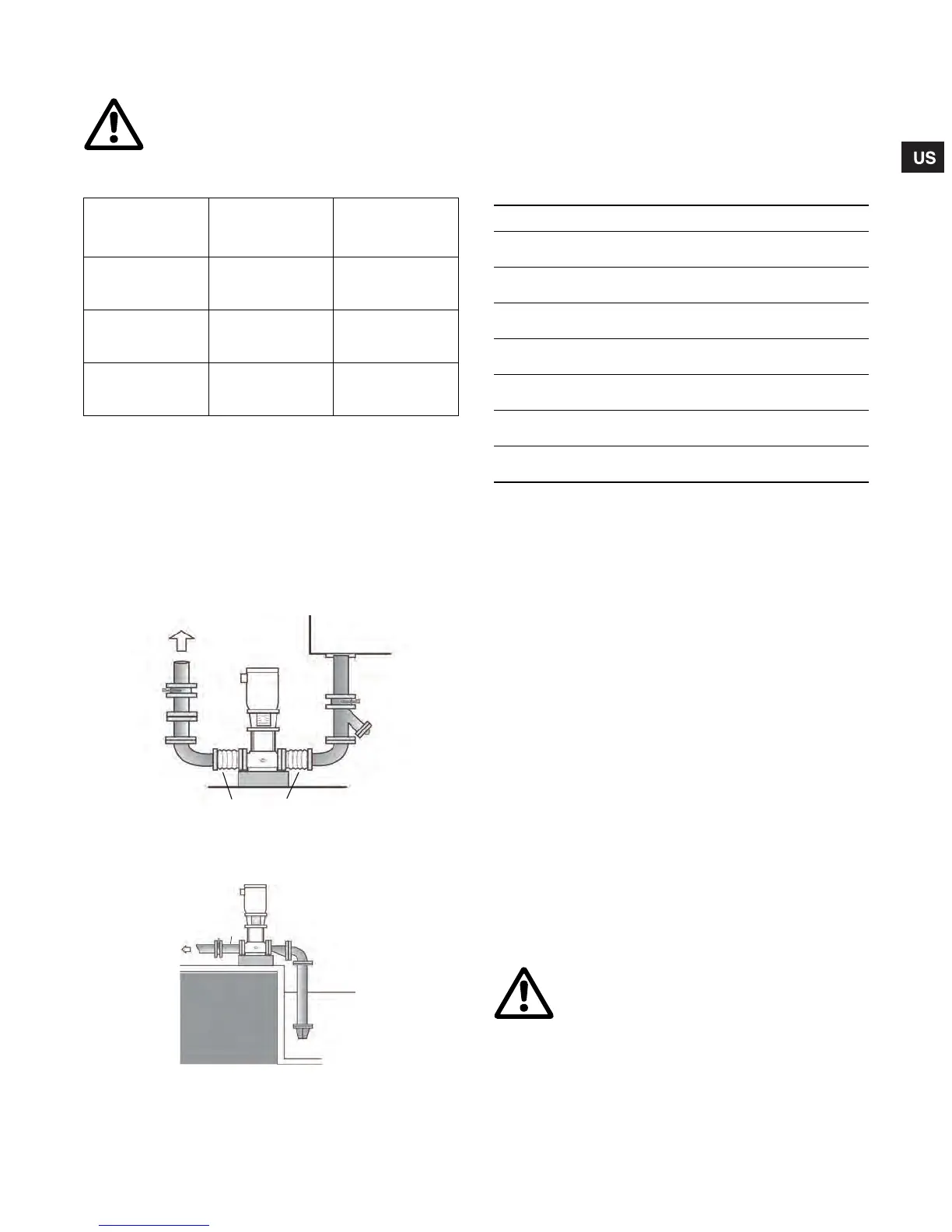
The suction pipe should be adequately sized and run as straight and
short as possible to keep friction losses to a minimum (minimum of
four pipe diameters straight run prior to the suction flange). Avoid
using unnecessary fittings, valves or accessory items. Butterfly or
gate valves should only be used in the suction line when it is
necessary to isolate a pump because of a flooded suction condition.
This would occur if the water source is above the pump; see fig. 5
and fig. 6. Flush piping prior to pump installation to remove loose
debris.
Fig. 5 Flooded suction
Fig. 6 Suction lift*
*The suction pipe should have a fitting on it for priming.
CRN-SF pumps cannot be used for suction lift.
6.5 Minimum suction pipe sizes
The following recommended suction pipe sizes are the smallest
sizes which should be used with any specific CR pump type.
The suction pipe size should be verified with each installation to
ensure good pipe practices are being observed and excess
friction losses are not encountered.
High temperatures may require larger diameter pipes to reduce
friction and improve NPHSA.
6.6 Discharge piping
It is suggested that a check valve and isolation valve be installed
in the discharge pipe.
Pipe, valves and fittings should be at least the same diameter as
the discharge pipe or sized in accordance with good piping
practices to reduce excessive fluid velocities and pipe friction
losses.
Note: Pipe, valves and fittings must have a pressure rating equal
to or greater than the maximum system pressure.
Before the pump is installed it is recommended that the discharge
piping be pressure checked to at least the maximum pressure the
pump is capable of generating or as required by codes or local
regulations.
Whenever possible, avoid high pressure loss fittings, such as
elbows or branch tees directly on either side of the pump. The
piping should be adequately supported to reduce thermal and
mechanical stresses on the pump.
Good installation practice recommends the system be thoroughly
cleaned and flushed of all foreign materials and sediment prior to
pump installation. Furthermore, the pump should never be
installed at the lowest point of the system due to the natural
accumulation of dirt and sediment. If there is excessive sediment
or suspended particles present, it is advised a strainer or filter be
used. Grundfos recommends that pressure gauges be installed
on inlet and discharge flanges or in pipes to check pump and
system performance.
Warning
CR, CRI, CRN pumps are shipped with covered
suction and discharge. The covers must be
removed before the final pipe flange to pump
connections are made.
Model
Recommended
foundation torque
(ft - lbs)
Recommended
flange torque
(ft - lbs)
CR, CRI, CRN
1s/1/3/5, and
CRT 2/4
30 37 - 44
CR, CRI,
CRN 10/15/20, and
CRT 8/16
37 44 - 52
CR, CRN
32/45/64/90/
120/150
52 52 - 59
TM04 3925 0409
TM04 3910 0409
Reservoir
Butterfly
Valve
Butterfly
Valve
Strainer
Check
Valve
Expansion Joint
Butterfly
Valve
Check
Valve
Eccentric
Reducer
Suction
Pipe
Reservio
Foot
Valve
Model Min. suction pipe size
CR(I)(N) 1s, 1, 3; CRT 2 1"
Nominal diameter
sch 40 pipe
CR(I)(N) 5;
CRT 4
1-1/4"
Nominal diameter
sch 40 pipe
CR(I)(N) 10, 15, 20;
CRT 8, 16
2"
Nominal diameter
sch 40 pipe
CR(N) 32 2-1/2"
Nominal diameter
sch 40 pipe
CR(N) 45 3"
Nominal diameter
sch 40 pipe
CR(N) 64, 90 4"
Nominal diameter
sch 40 pipe
CR(N) 120, 150 5"
Nominal diameter
sch 40 pipe
Warning
To avoid problems with waterhammer, fast
closing valves must not be used in CRN-SF
applications.
Grundfos.bk Page 11 Wednesday, March 18, 2009 10:38 AM

 Loading...