18
10.2.1 Torque specifications for CR 1s, 1, 3, and 5
Insert shaft pin into shaft hole. Reinstall the coupling halves onto
shaft and shaft pin. Reinstall the coupling screws and leave
loose. Check that the gaps on either side of the coupling are
even, and that the motor shaft keyway is centered in the coupling
half, as shown in fig. 16.
Tighten the screws to the correct torque; see torque
specifications table below.
10.2.2 CR 10, 15 and 20
Insert shaft pin into shaft hole. Insert plastic shaft seal spacer
beneath shaft seal collar. Reinstall the coupling halves onto shaft
and shaft pin. Reinstall the coupling screws and leave loose.
Check that the gaps on either side of the coupling are even and
that the motor shaft key way is centered in the coupling half, as
shown in fig. 16. Tighten the screws to the correct torque.
Remove plastic shaft seal spacer and hang it on inside of
coupling guard.
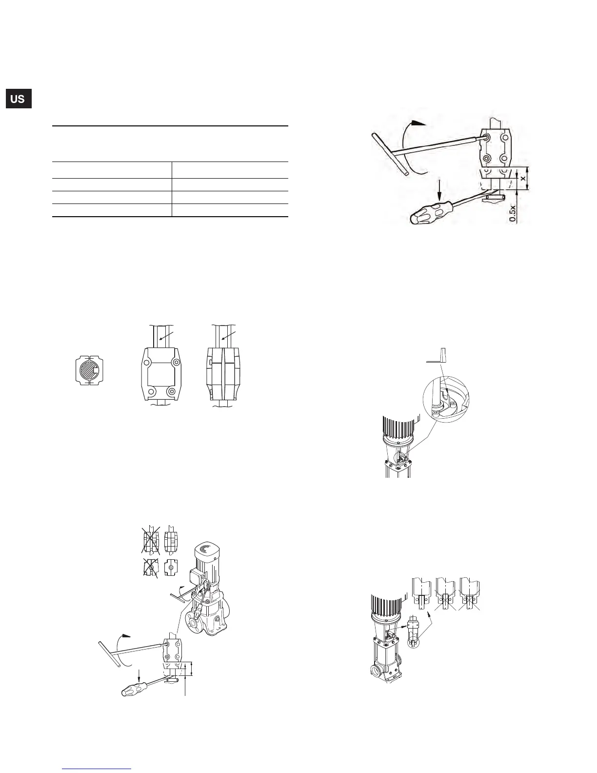
Fig. 16 Coupling adjustment all CR(I)(N)(X)(T)
10.2.3 CRT 2, 4, 8 and 16
Reinstall coupling halves. Make sure the shaft pin is located in
the pump shaft. Put the cap screws loosely back into the coupling
halves.
Using a large screwdriver, raise the pump shaft by placing the tip
of the screwdriver under the coupling and carefully elevating
coupling to its highest point; see fig. 17.
Fig. 17 Coupling adjustment CRT 2, 4, 8, and 16
Note: The shaft can only be raised approximately 0.20 in (5mm).
Now lower the shaft halfway back down the distance you just
raised it and tighten the coupling screws (finger tight) while
keeping the coupling separation equal on both sides. When the
screws are tight enough to keep the couplings in place, then
torque the screws evenly in a criss-cross pattern.
Fig. 18 Coupling adjustment clearance CRT 2, 4, 8, and 16
10.2.4 CR(N) 32, 45, 64, 90, 120, and 150
1. Make sure shaft is all the way down. TIghten the set screws on
the mechanical seal.
2. Place the plastic adjustment fork under the cartridge seal
collar; see fig. 19.
Fig. 19 Coupling adjustment
CR(N) 32, 45, 64, 90, 120, and 150
3. Fit the coupling on the shaft so that the top of the pump shaft
is flush with the bottom of the clearance chamber in the
coupling; see fig. 20.
Note: To avoid damaging the coupling halves, ensure that no
portion of the keyway on the motor shaft lies within the gap
between the two coupling halves.
Fig. 20 Coupling adjustment clearance
CR(N) 32, 45, 64, 90, 120, and 150
Torque specifications
CR(I)(N) 1s, 1, 3, 5, 10, 15, and 20
CRT 2, 4, 8, and 16
Coupling bolt size Min. torque
M6 10 ft-lb
M8 23 ft-lb
M10 46 ft-lb
TM04 3919 0409
TM02 1051 0501
CORRECT
CORRECT NOT CORRECT
TOP
View
Gap between coupling
Keyway Keyway
M6 - 13 Nm
M8 - 31 Nm
M10 - 62 Nm
0.5x
x
TM02 1051 0501TM04 3913 0409
TM04 3914 0409
• Note the
clearance
below the
coupling
• Raise the
coupling higher,
as far as it will go
• Lower it halfway
back down
(1/2 the distance
you just raised it)
• Tighten screws
(see torque
specifications
below)
Grundfos.bk Page 18 Wednesday, March 18, 2009 10:38 AM

 Loading...