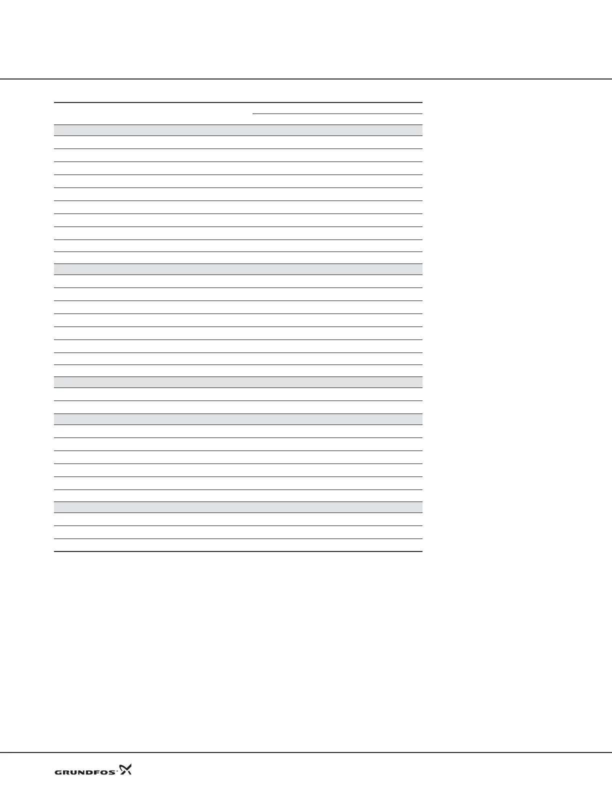
Functions
Grundfos CUE
12
* The PC Tool is a software program supplied on a CD and hardware con-
necting your computer with the CUE.
Digital inputs, see page 27
Start/stop
z
Min. (Min. curve)
z
Max. (Max. curve)
z
External fault
z
Flow switch
z
Alarm reset
z
Dry running (from external sensor)
z
Accumulated flow (from pulse flow sensor)
z
Additional set of ramps, ramp selector
Predefined setpoints from digital input
Signal relays, see page 28
Ready
z
Warning
z
Alarm
z
Operation
z
Pump running
z
Relubricate
z
External relay control
Limit exceeded
Analog inputs, see page 28
External setpoint
z
Sensor 1
z
Analog output, see page 28
Feedback value
Speed
Frequency
Motor current
External setpoint input
Limit exceeded
MCB 114 sensor input module, see page 29
Sensor input 2
z
Temperature sensor 1
z
Temperature sensor 2
z
CUE functions
Setting or reading via:
CUE GENIbus PC Tool*
z
Default
Optional with GENIbus
Optional with PC-tool
 Loading...


