Functions
Grundfos CUE
23
Constant level with stop function
The purpose of the stop function is to stop the pump
when low or no flow is detected.
Note: It
is only possible to set constant level with stop
function if the system incorporates a level sensor, and
all valves can be closed.
When low flow is detected, the pump is in on/off opera-
tion. If there is flow, the pump will continue operating
accord
ing to the setpoint. See fig. 25.
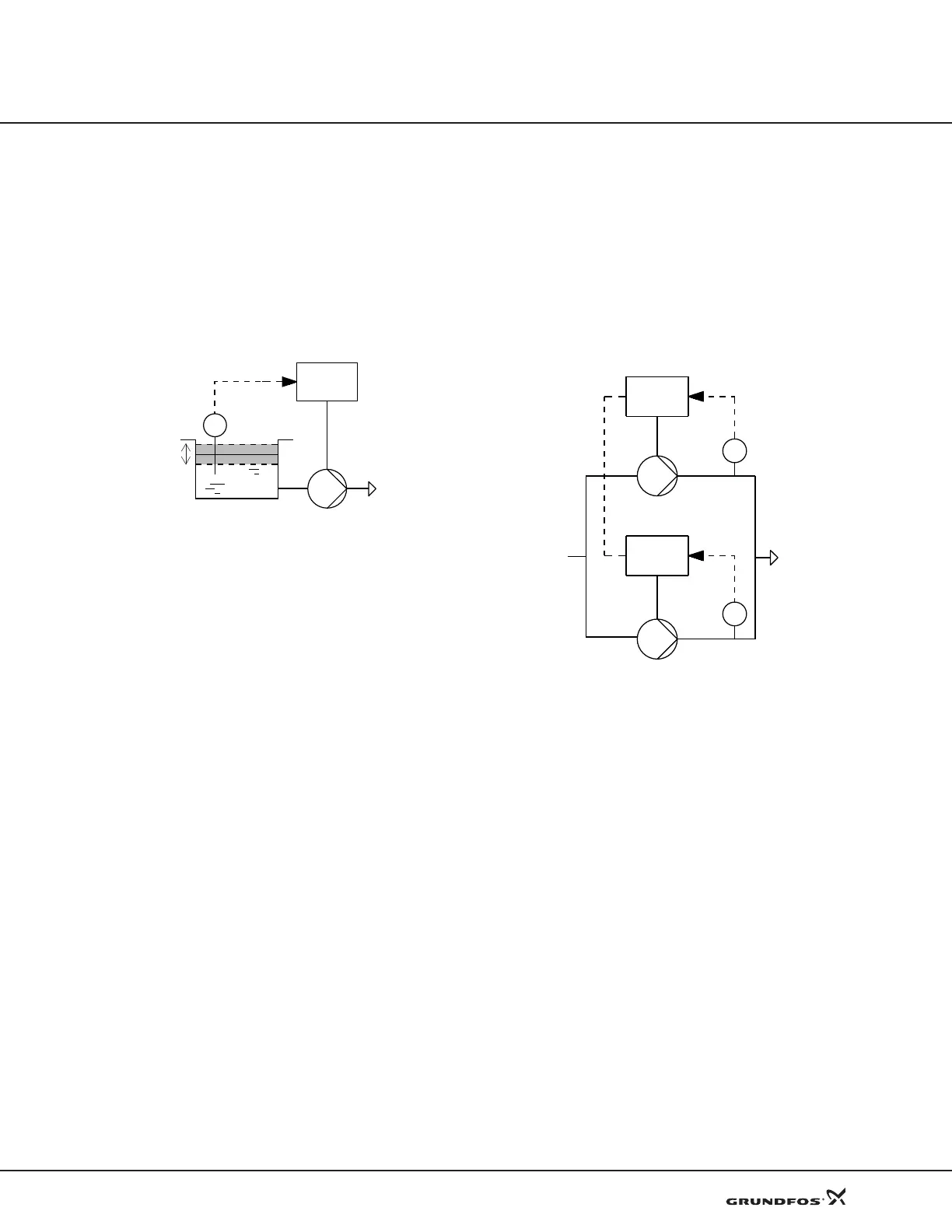
Fig. 25 Constant level with stop function. Difference be-
tween start and stop levels (ΔH)
Low flow can be detected in two different ways:
• with the built-in low-flow detection function
• with a flow switch connected to a digital input.
Low-flow detection function
The low-flow detection function will check the flow reg-
ularly by measurement of speed and power.
Low-flow detection with flow switch
When a flow switch detects low flow, the digital input
w
ill be activated.
Dry-running protection
This function protects the pump against dry running.
When lack of inlet pressure or water shortage is
detected, the pump will be stopped before being dam-
aging.
Lack of inlet pressure or water shortage can be
dete
cted in two ways:
• With a switch connected to a digital input configured
t
o dry-running protection.
• The CUE checks if the shaft power is below a dry-
pump limit for a configurable time (setting via PC
Tool).
The use of a digital input requires an accessory, such
as:
• a Grundfos Liqtec
®
dry-running switch
• a pressure switch installed on the suction side of the
pump
• a float switch installed on the suction side of the
pump.
The pump cannot restart as long as the input is acti-
vated. Restart may be delayed by up to 30 minutes,
dep
ending of the pump family.
Duty/standby
The built-in duty/standby function applies to two pumps
connected in parallel to ensure reliability of supply. See
fig. 26.
Fig. 26 Two pumps connected in parallel and controlled
via GENIbus
These are the primary purposes of the function:
• To let one pump run at a time.
• To start the standby pump if the duty pump stops
due to an alarm.
• To alternate the pumps at least every 24 hours.
Description
The two pumps are electrically connected by means of
th
e GENIbus interface. Each pump must be connected
to its own CUE and sensor.
Note: The t
wo pumps running duty/standby in this way
cannot use the GENIbus interface for remote communi-
cation.
The function is activated via the control panel.
Operating mode
The two pumps use their own local operating mode. For
inst
ance, pump 1 can operate in Normal mode, and
pump 2 can operate in Max. mode.
Control mode
Both pumps must have the same control mode.
TM03 8809 2607
Start level
ΔH
Stop level
CUE
L
TM04 0368 0608
CUE
p
CUE
p

 Loading...


