Accessories
Grundfos CUE
53
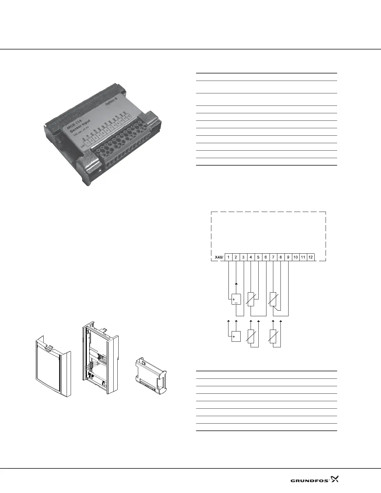
MCB 114 sensor input module
Fig. 53 MCB 114 sensor input module
The MCB 114 offers three additional analog inputs for
the CUE:
• one analog 0/4-20 mA input for an additional sensor
• two analog Pt100/Pt1000 inputs for temperature
senso
rs.
The three analog inputs are default used for monitoring.
For
further information, see section MCB 114 sensor
input module on page 29.
Scope of delivery
The MCB 114 comes with a terminal cover, an
extend
ed frame and an identification label to put onto
the CUE.
Fig. 54 Scope of delivery
Technical data
All analog inputs are galvanically separated from the
suppl
y voltage (PELV) and other high-voltage termi-
nals.
Wiring diagram
Fig. 55 Wiring diagram, MCB 114
Terminals 10, 11 and 12 are not used
TM04 0293 0308TM04 0026 4807
Extended frame
Terminal cover
MCB 114 sensor
input module
Relative humidity 5-95% RH
Ambient temperature during operation
14 to 131° F
(–10 to 55° C)
Temperature during storage and transportation
–13 to 158° F
(–25 to 70° C)
Maximum length, signal cable 984 ft (300 m)
Analog input 3
Terminal number 2
Current range 0/4-20 mA
Input resistance < 200 Ω
Analog inputs 4 and 5
Terminal number 4, 5 and 7, 8
Signal type, 2- or 3-wire Pt100/Pt1000
TM03 9483 4007
Terminal Type Function
1 +24 V out Supply to sensor
2 AI 3 Sensor 2, 0/4-20 mA
3 GND Common frame for analog input
4, 5 AI 4 Temperature sensor 1, Pt100/Pt1000
6 GND Common frame for temperature sensor 1
7, 8 AI 5 Temperature sensor 2, Pt100/Pt1000
9 GND Common frame for temperature sensor 2
0/4-20 mA
+24 V out
Sensor 2
GND
GND
GND
Temperature
sensor 1
Temperature
sensor 2
3-wire
2-wire
 Loading...


