Accessories
Grundfos CUE
58
Grundfos differential pressure
sensor, DPI
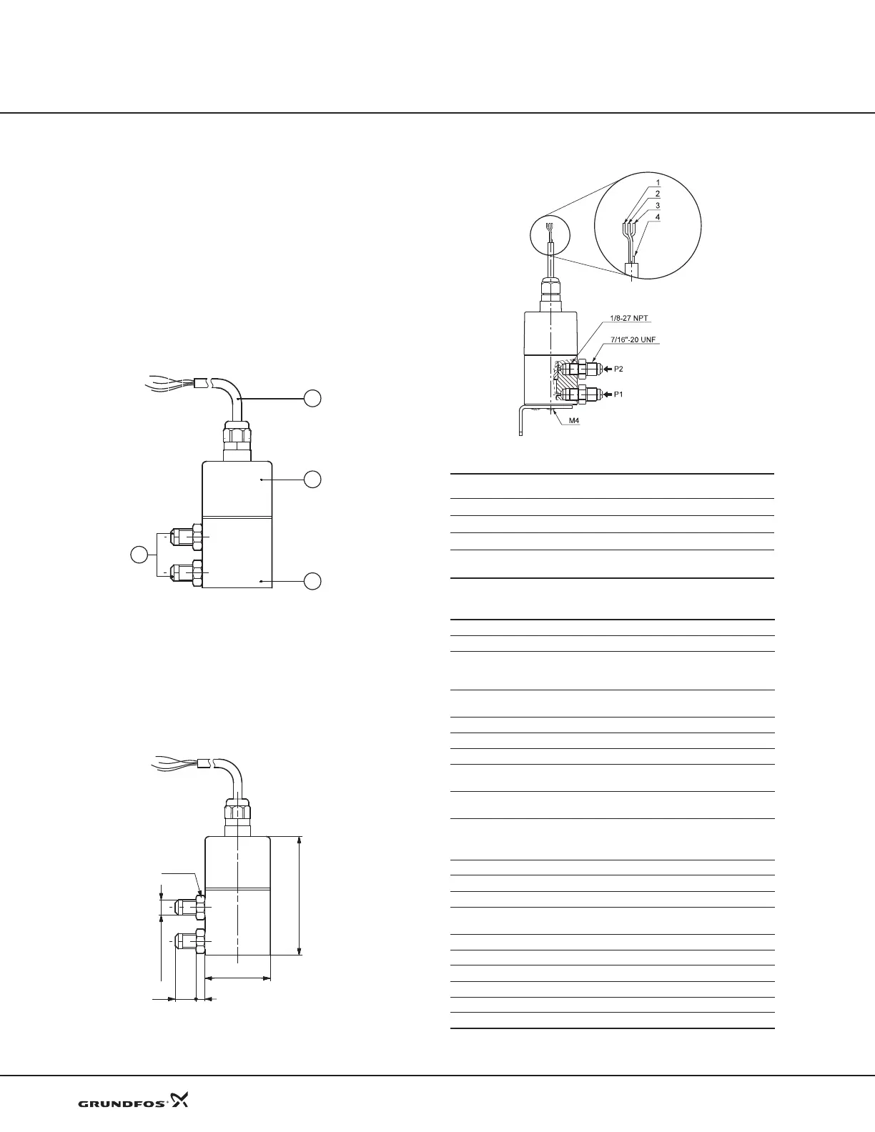
Product description
A cable (pos. 1) goes through an M12 x 1.5 pg connec-
tion. See fig. 65.
The sensor housing and parts in contact with the
medium a
re made of Inox DIN W.-Nr. 1.4305 (pos. 3)
with composite PA top (pos. 2). The pressure connec-
tions (pos. 4) are DIN W.-Nr. 1.4305, 7/16” UNF, and
gaskets are FKM.
Fig. 65 DPI position numbers
The sensor is supplied with angular bracket for mount-
ing on motor or bracket for wall mounting. See fig. 67.
Options with other cable lengths and various fitting con-
nectors are available.
Dimensions
Fig. 66 Dimensions, DPI
Wiring diagram
Fig. 67 Wiring diagram, DPI
Technical data
TM03 2057 3505TM03 2059 3505
7/16 - 20 UNF
ø45
77
614
SW 14
P2
P1
TM03 2225 3905
No Colour
Function
1 Brown Supply voltage, 12-30 V
2 Yellow GND
3 Green Control signal
4White
Test signal. Must not be connected to supply voltage
(conductor can be cut off)
Supply voltage 12-30 VDC
Output signal 4-20 mA
Load [Ω]
24 V: max. 500 [Ω]
16 V: max. 200 [Ω]
12 V: max. 100 [Ω]
Max. system pressure,
P1 and P2 simultaneously
232 psi (16 bar)
Rupture pressure [bar] 1.5 x system pressure
Measuring accuracy 2.5% BFSL
Response time < 0.5 sec
Media temperature range
+14 °F to +158 °F
(–10 °C to +70 °C)
Storage temperature range
–40 °F to 176 °F
(–40 °C to +80 °C)
Electrical connection
3-wire 0.13 mm
2
2.9 ft (0.9 m) cable
M12 x 1.5 in sensor top
Short-circuit proof Yes
Protected against reverse polarity Yes
Over supply voltage Yes
Materials in contact with medium
DIN W.-Nr. 1.4305
FKM and PPS
Enclosure class IP55
Weight 550 g
EMC (electromagnetic compatibility) According to EN 61326-1
Emission/immunity According to EN 61326-1
Connections 7/16”-UNF
Sealing material FKM
 Loading...


