Grundfos CUE
31
Installation
Mechanical installation
The CUE cabinet sizes are characterised by their
enclosure. The CUE is available in three enclosure
classes: IP21, IP54 and IP55. To see the relationship of
enclosure class and enclosure type, see tables starting
on page 41.
The general installation requirements necessitate spe-
cial considerations as to these aspects:
• Enclosure class IP54/55 must be installed freely ac-
cessible, but must not be installed outdoors without
ad
ditional protection against water and the sun.
• The CUE contains a large number of mechanical
an
d electronic components and must therefore not
be installed in an environment where the air con-
tains liquids, particles or gasses which may affect
an
d damage the electronic components.
• In applications requiring Ex approval, the CUE
shou
ld be installed outside the hazardous area.
Space requirements and air circulation
CUE units can be mounted side by side, but as a suffi-
cient air circulation is required for cooling, these
requ
irements must be met:
• Sufficient free space above and below the CUE.
S
ee table below.
• Hang the CUE directly on the wall, or fit it with a
ba
ck plate to secure sufficient air flow for cooling.
See fig. 36.
Fig. 36 CUE hung directly on the wall or fitted with a back
plate
Required free space above and below the CUE
Required free space in front of the CUE
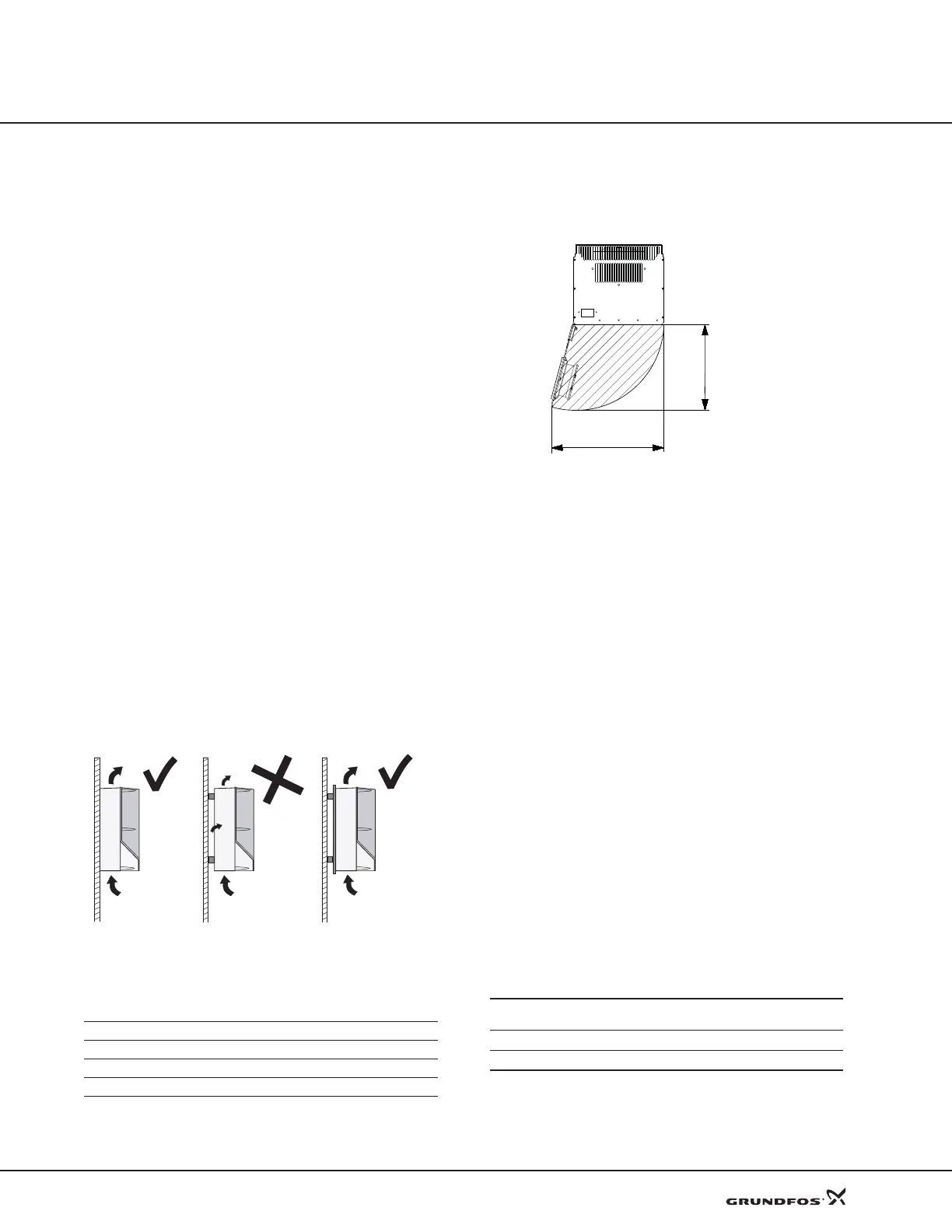
Furthermore, there must be sufficient space in front of
the CUE for opening the door of the CUE. See fig. 37.
Fig. 37 Free space in front of CUE enclosures D1 and D2
Ventilation of built-in CUE
The CUE can be mounted in a control cabinet if suffi-
cient air circulation is ensured. The quantity of air flow
r
equired for cooling the CUE can be calculated as fol-
lows:
Insert P in Watt and ΔT in F (Fahrenheit.
P is the power loss of all equipment integrated in the
same cabinet
. Calculate the power loss P of the CUE by
means of the typical shaft power P2 multiplied by the
efficiency.
ΔT
is the difference between the outlet temperature and
the inlet temperature (ambient) of the cooling air. See
fig. 36.
Note: T
he inlet and outlet temperatures must not be
higher than the values in the table below.
The average inlet temperature over 24 hours must be
9 °F lower.
TM03 8859 2607
Enclosure Space - in [mm]
A2, A3, A5 4 (100)
B1, B2, B3, B4, C1, C3 8 (200)
C2, C4, D1, D2 9 (225)
Inlet
temperature
Outlet
temperature
TM03 9897 4607
Output current
Max. inlet
temperature
Max. outlet
temperature
Up to 177 amps
122 °F (50 °C) 131 °F (55 °C)
Over 177 amps
113°F (45 °C) 122 °F (50 °C)
15.7 in.
21.0 in.
q
v
P
¦
3.285×
ΔT
--------------------------------= ft
3
/ min[]
 Loading...


