Functions
Grundfos CUE
21
PID controller
The CUE has a built-in PID controller for speed control
of pumps. The factory setting of gain (K
p
) and integral
time (T
i
) can easily be changed in the control panel.
The controller can operate in both normal and inverse
mode.
Normal mode
Normal mode is used in systems in which an increase
in p
ump performance will result in a rise in the value
measured at the feedback sensor. This will typically be
the case in most CUE applications.
Normal mode is selected by setting the gain (K
p
) to a
positive value in the control panel.
Inverse mode
Inverse mode is used in systems in which an increase
in p
ump performance will result in a drop in the value
measured at the feedback sensor. This mode will typi-
cally be used for constant level operation (emptying
tank)
and for constant temperature operation in cooling
systems.
Inverse mode is selected by setting the gain (K
p
) to a
negative value in the control panel.
Description
The PID controller compares the requ
ired setpoint
(p
set
) with the actual value (p) measured by the trans-
mitter (P). See fig. 21.
Fig. 21 Constant pressure control
If the measured value is higher than the required set-
point, the PID controller will reduce the speed and the
perf
ormance of the pump until the measured value is
equal to the required setpoint.
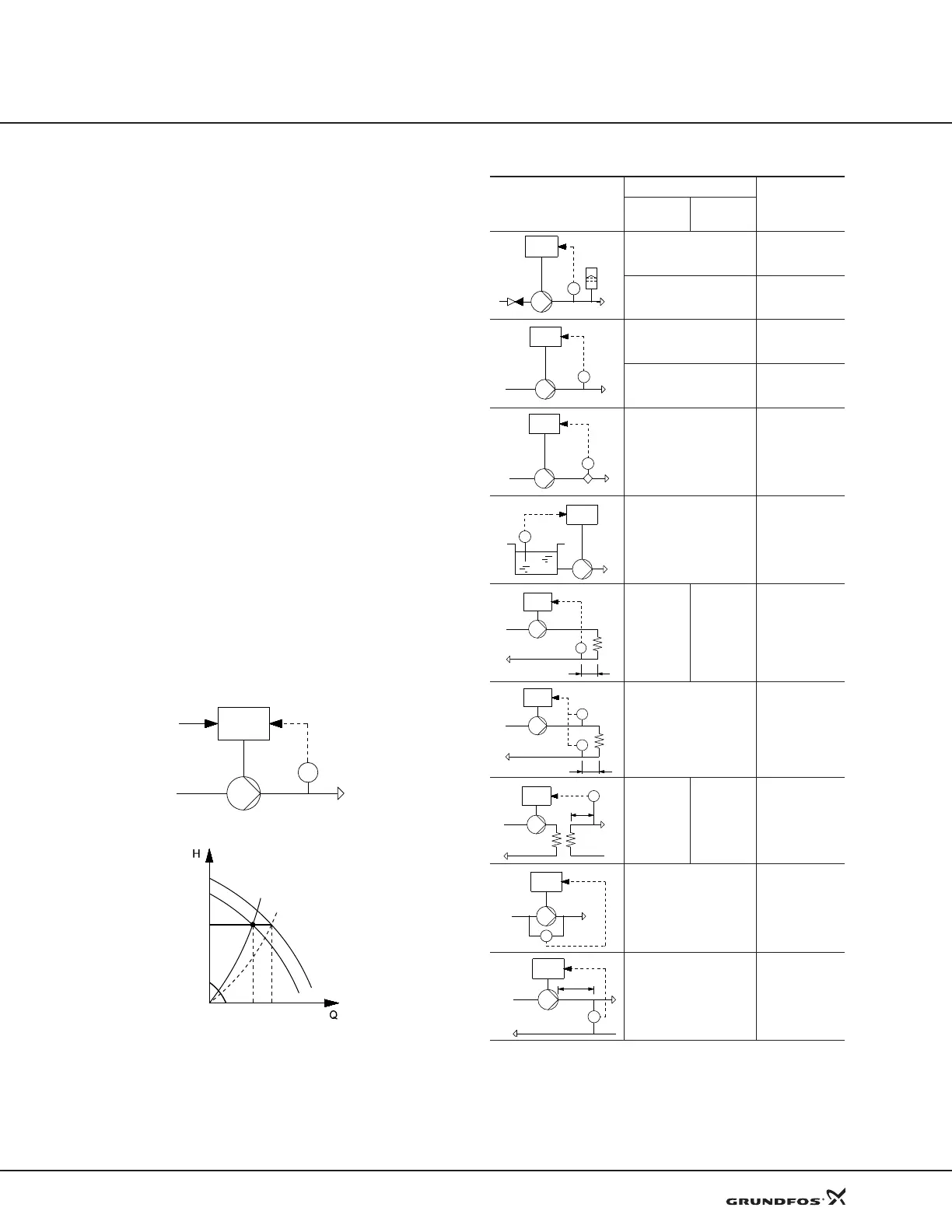
Suggested controller settings
*Ti = 100 seconds (factory setting).
Heating systems are systems in which an increase in pump performance
will result in a rise in temperature at the sensor.
Cooling systems are systems in which an increase in pump performance
will result in a drop in temperature at the sensor.
L
1
=Distance in [m] between pump and sensor.
L
2
=Distance in [m] between heat exchanger and sensor.
TM04 0367 0608
Setpoint p
set
Measured value p
P
CUE
p
set
QQ
max
System/application
K
p
T
i
Heating
system
1)
Cooling
system
2)
0.2 0.5
SP, SP-G, SP-NE: 0.5 0.5
0.2 0.5
SP, SP-G, SP-NE: 0.5 0.5
0.2 0.5
–2.5 100
0.5 –0.5
10 + 5L
2
0.5
10 + 5L
2
0.5 –0.5
30 + 5L
2
*
0.5 0.5*
0.5
L
1
< 5 m: 0.5*
L
1
> 5 m: 3*
L
1
> 10 m: 5*
CUE
p
CUE
p
CUE
Q
CUE
L
t
L
2
CUE
Δt
L
2
CUE
CUE
Δp
Δp
L
1
CUE
 Loading...


