Functions
Grundfos CUE
15
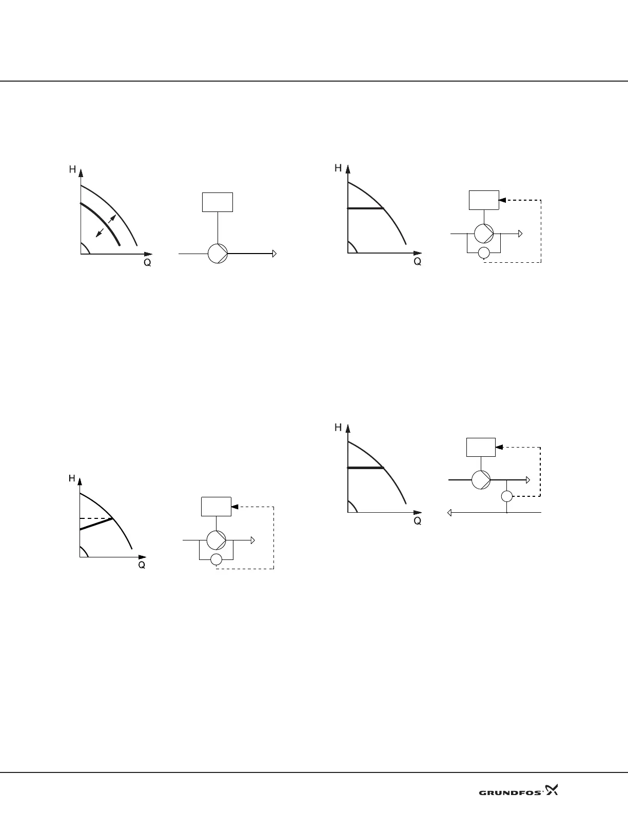
Open loop, constant curve
The speed is kept at a set value in the range between
the min. and max. curves. See fig. 4.
Fig. 4 Open loop, constant curve
In control mode Open loop, the setpoint is set in% of the
nominal speed. The setting range will lie between the
min. and max. curves.
Operation on constant curve can for instance be used
for
pumps with no sensor connected.
This control mode is also typically used in connection
w
ith an overall control system such as Control MPC or
another external controller.
Proportional differential pressure
The differential pressure of the pump is reduced at fall-
ing flow rate and increased at rising flow rate. See fig. 5.
Fig. 5 Proportional differential pressure
The pump is controlled according to a differential pres-
sure measured across the pump. This means that the
pump system offe
rs a proportional differential pressure
in the Q-range of 0 to Q
max.
, represented by the sloping
line in the QH diagram.
Constant differential pressure, pump
The differential pressure of the pump is kept constant,
independently of the flow rate. See fig. 6.
Fig. 6 Constant differential pressure, pump
The pump is controlled according to a constant differen-
tial pressure measured across the pump. This means
th
at the pump system offers constant differential pres-
sure in the Q-range of 0 to Q
max.
, represented by the
horizontal line in the QH diagram.
Constant differential pressure, system
The differential pressure of the system is kept constant,
independently of the flow rate. See fig. 7.
Fig. 7 Constant differential pressure, system
The pump is controlled according to a constant differen-
tial pressure measured across the system. This means
th
at the pump offers constant differential pressure of
the system in the Q-range of 0 to Q
max.
, represented by
the horizontal line in the QH diagram.
TM03 8479 1607
TM03 9727 4307
TM03 8475 1607
TM03 8804 2507
CUE
Q
max.
Δp
CUE
TM03 8476 1607
TM03 8804 2507
TM03 8476 1607
TM03 8806 2507
CUE
Δp
Δp
CUE
 Loading...


