Installation
Grundfos CUE
33
Mains and motor connection
The supply voltage and frequency are marked on the
CUE nameplate. Make sure that the CUE is suitable for
the electricity supply of the installation site.
Mains switch
A mains switch can be installed before the CUE accord-
ing to local regulations. See fig. 38.
Wiring diagram
The wires in the terminal box must be as short as pos-
sible. Excepted from this is the protective conductor
w
hich must be so long that it is the last one to be dis-
connected in case the cable is inadvertently pulled out
of
the cable entry.
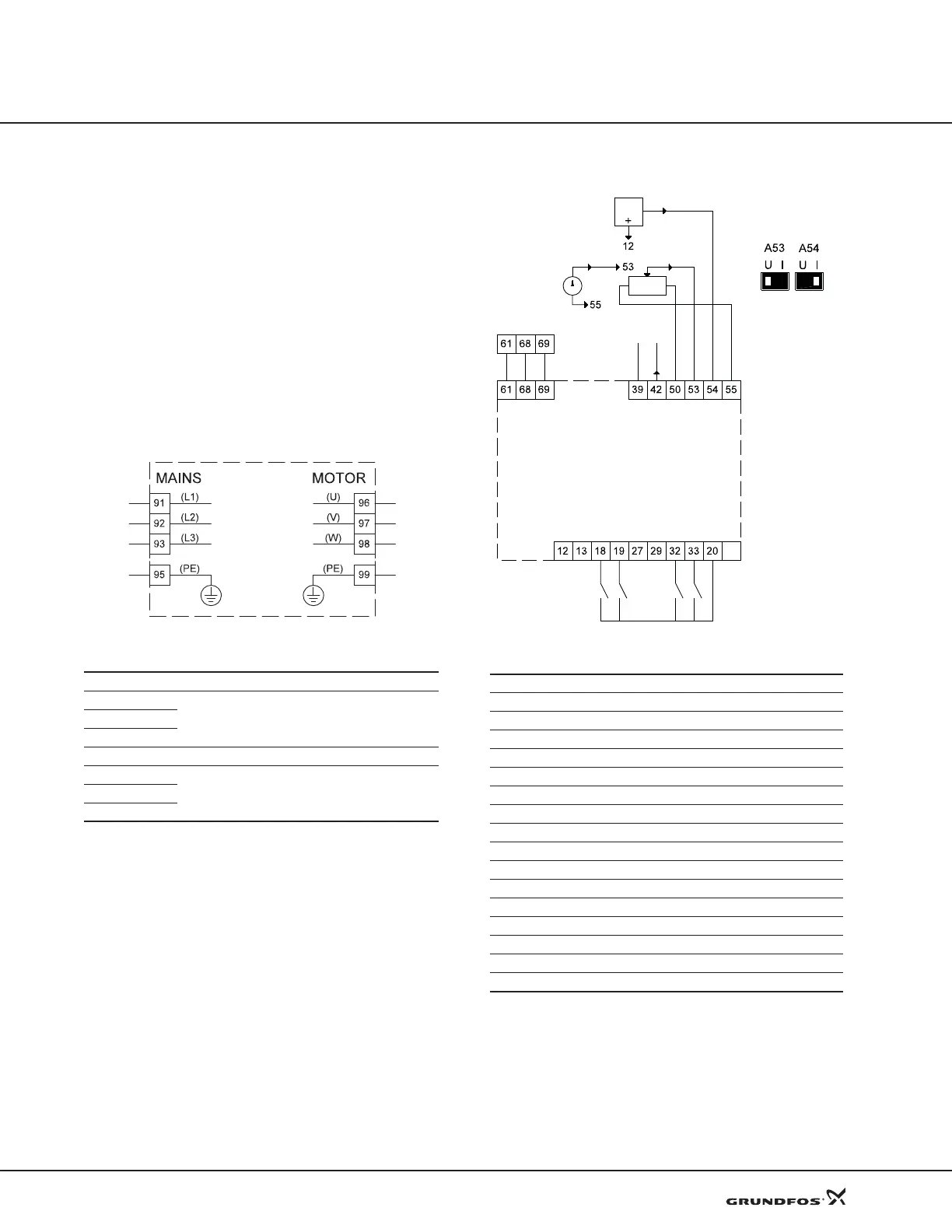
Fig. 39 Wiring diagram, three-phase mains connection
Note: use terminals 91 and 92 for single phase CUE’s.
Connecting the signal terminals
Note: As a precaution, signal cables must be separated
from other groups by reinforced insulation in their entire
lengths.
Note: If
no external on/off switch is connected, short-
circuit terminals 18 and 20 using a short wire.
Wiring diagram, signal terminals
Fig. 40 Wiring diagram, signal terminals
Terminals 27 and 29 are not used.
Connect the signal cables according to the guidelines
for good practice to ensure EMC-correct installation.
See section EMC-correct installation,35.
• Use shielded signal cables.
• Use a 3-conductor shielded bus cable.
TM03 8799 2507
Terminal Function
91 (L1)
Three-phase supply92 (L2)
93 (L3)
95/99 (PE) Earth connection
96 (U)
Three-phase motor connection, 0-100 % of mains
voltage
97 (V)
98 (W)
TM03 8800 2507
Terminal Type Function
12 +24 V out Supply to sensor
13 +24 V out Additional supply
18 DI 1 Digital input, start/stop
19 DI 2 Digital input, programmable
20 GND Common frame for digital inputs
32 DI 3 Digital input, programmable
33 DI 4 Digital input, programmable
39 GND Frame for analog output
42 AO 1 Analog output, 0-20 mA
50 +10 V out Supply to potentiometer
53 AI 1 External setpoint, 0-10 V, 0/4-20 mA
54 AI 2 Sensor input, sensor 1, 0/4-20 mA
55 GND Common frame for analog inputs
61 RS-485 GND Y GENIbus, screen (frame)
68 RS-485 A GENIbus, signal A (+)
69 RS-485 B GENIbus, signal B (-)
+24 V out
+24 V out
DI 2
DI 3
DI 4
GND
GND
AO 1
+10 V out
Ext. setpoint
Sensor 1
GND
RS-485 GND Y
RS-485 A
RS-485 B
0/4-20 mA
1 K
0-20 mA
4-20 mA
0-10 V, 4-20 mA
Start/stop
Terminals
53 and 54:
U = 0-10 V
I = 4-20mA
 Loading...


