English (GB)
6
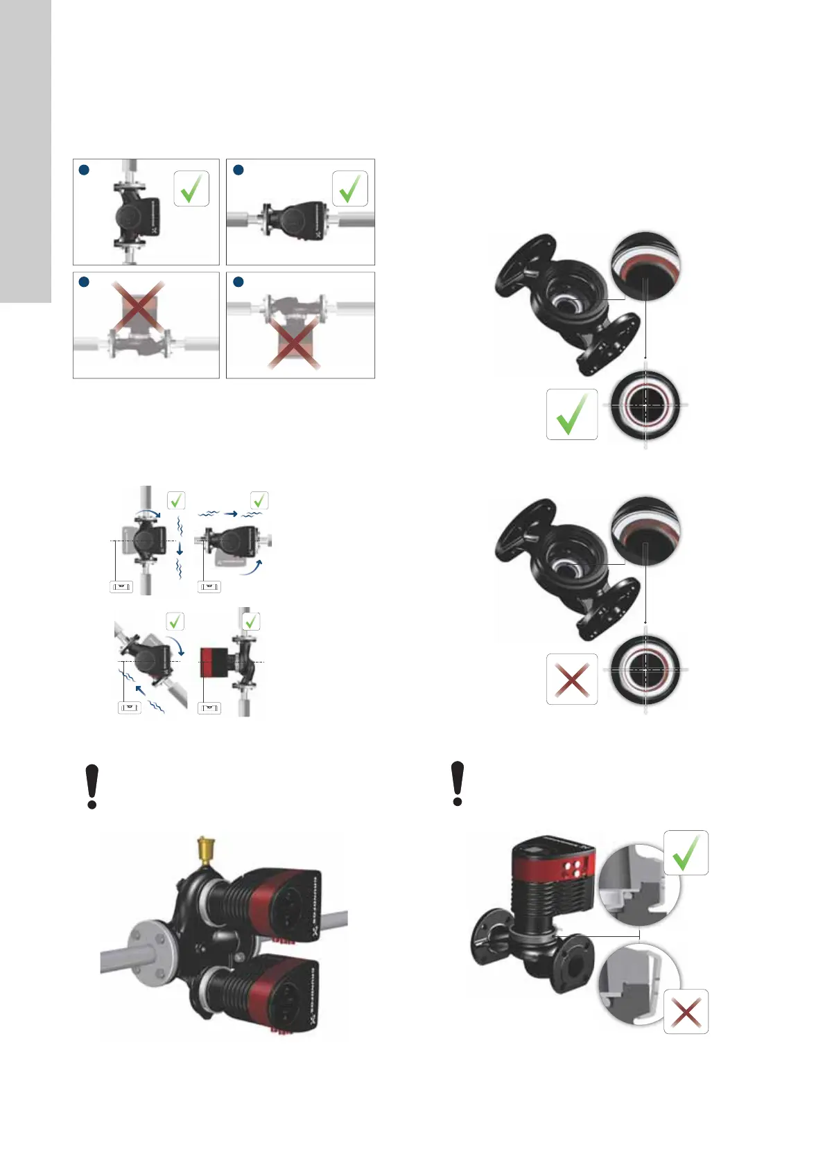
3.3.1 Pump positions
Always install the pump with horizontal motor shaft.
• Pump installed correctly in a vertical pipe. See fig. 6, pos. A.
• Pump installed correctly in a horizontal pipe. See fig. 6, pos. B.
• Do not install the pump with vertical motor shaft. See fig. 6,
pos. C and D.
Fig. 6 Pump installed with horizontal motor shaft
3.3.2 Control box positions
To ensure adequate cooling, make sure that the control box is in
horizontal position with the Grundfos logo in vertical position. See
fig. 7.
Fig. 7 Pump with control box in horizontal position
Fig. 8 Automatic vent
3.3.3 Pump head position
If you remove the pump head before installing the pump in the
pipes, pay special attention when fitting the pump head to the
pump housing:
1. Visually check that the floating ring in the sealing system is
centred. See figs 9 and 10.
2. Gently lower the pump head with rotor shaft and impeller into
the pump housing.
3. Make sure that the contact face of the pump housing and that
of the pump head are in contact before you tighten the clamp.
See fig. 11.
Fig. 9 Correctly centred sealing system
Fig. 10 Incorrectly centred sealing system
Fig. 11 Fitting the pump head to the pump housing
TM05 5518 3016TM05 5522 3016
Fit twin-head pumps installed in horizontal pipes with
an automatic air vent, Rp 1/4, in the upper part of the
pump housing. See fig. 8.
TM05 6062 3016
TM05 6650 3016TM05 6651 3016
Check the position of the clamp before you tighten it.
Incorrect position of the clamp will cause leakage
from the pump and damage the hydraulic parts in the
pump head. See fig. 11.
TM05 5837 3016
 Loading...


