TM038732
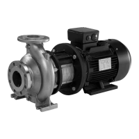
Example of connection of a 3-conductor bus cable with screen
connected at both ends
Pos. Description
1 Controller
2 CUE
TM038731
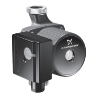
Example of connection of a 3-conductor bus cable with screen
connected to CUE (controller with no cable clamps)
Pos. Description
1 Controller
2 CUE
6.3 RFI filters
To meet the EMC requirements, CUE comes with the following
types of built-in radio-frequency interference filters (RFI).
Voltage [V]
Typical shaft power P2
[kW (hp)]
RFI filter type
1 x 200-240
1)
1.1 - 7.5
(1.5 - 10)
C1
3 x 200-240
0.75 - 45
(1 - 60)
C1
3 x 380-500
0.55 - 90
(0.75 - 125)
C1
3 x 380-500
110 - 250
(150 - 350)
C3
3 x 525-600
0.75 - 90
(1 - 125)
C3
3 x 525-690
11 - 250
(15 - 350)
C3
1)
Single-phase input - three-phase output.
Description of RFI filter types
C1:
For use in domestic areas.
C3:
For use in industrial areas with own low-voltage
transformer.
RFI filter types are according to EN 61800-3.
Equipment of category C3
• This type of power drive system (PDS) is not intended to be
used on a low-voltage public network which supplies domestic
premises.
Related information
6.7.2 Fitting MCB 114 in CUE
6.4 Mains and motor connection
Check that the mains voltage and frequency correspond
to the values on the nameplate of CUE and the motor.
The motor cable must be screened for CUE to meet EMC
requirements.
The supply voltage and frequency are marked on the CUE
nameplate. Make sure that CUE is suitable for the power supply
of the installation site.
6.4.1 Main switch
A main switch can be installed before the CUE cabinet according
to local regulations. See figure Example of three-phase mains
connection of CUE with main switch, backup fuses and additional
protection.
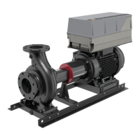
6.4.2 Wiring diagram
The wires in the terminal box must be as short as possible.
Excepted from this is the protective conductor which must be so
long that it is the last one to be disconnected in case the cable is
inadvertently pulled out of the cable entry.
TM038799
Wiring diagram, three-phase mains connection
Terminal Function
91 (L1)
Three-phase mains supply92 (L2)
93 (L3)
95/99 (PE) Protective earth connection
96 (U)
Three-phase motor connection, 0-100 % of mains
voltage
97 (V)
98 (W)
10
English (US)