At low air pressure, the cooling capacity of air is reduced, and CUE
automatically reduces the performance to prevent overload.
It may be necessary to select a CUE unit with a higher
performance.
5. Mechanical installation
The individual CUE cabinet sizes are characterised by their
enclosures. The table in section Enclosure shows the relationship
between enclosure class and enclosure type.
Related information
11.1 Enclosure
5.1 Enclosure types
Products with integrated STO function must be installed in an IP54
cabinet according to IEC 60529 or in an equivalent environment. In
special applications, a higher IP degree may be necessary.
5.2 Location
To ensure sufficient motor and CUE cooling, leave at least 50 mm
between the end of the fan covers of both motor and CUE and a
wall or another fixed object.
6. Electrical connection
WARNING
Electric shock
Death or serious personal injury
‐ Before starting any work on the product, make sure
that the power supply has been switched off and that it
cannot be accidentally switched on. See section
Installation requirements.
‐ Touching the electrical parts may be fatal, even after
CUE has been switched off.
Voltage Min. waiting time
4 minutes 15 minutes 20 minutes
200-240 V
0.75 - 3.7 kW
(1 - 5 hp)
5.5 - 45 kW
(7.5 - 60 hp)
380-500 V
0.55 - 7.5 kW
(0.75 - 10 hp)
11 - 90 kW
(15 - 125 hp)
110 - 250 kW
(150 - 350 hp)
525-600 V
0.75 - 7.5 kW
(1 - 10 hp)
11 - 90 kW
(15 - 125 hp)
525-690 V
11 - 250 kW
(15 - 350 hp)
WARNING
Electric shock
Death or serious personal injury
‐ Before carrying out any work, ensure that the motor is
not rotating. Even when not supplied with power, there
is voltage at the terminals of a rotating magnet-
assisted reluctance motor.
The owner or installer is responsible for ensuring correct
earthing and protection according to local standards.
For products with STO, ensure short-circuit protection of
the cable between terminal 37 and the external safety
device.
Security measures are the responsibility of the user.
The frequency converter parameters can be password
protected.
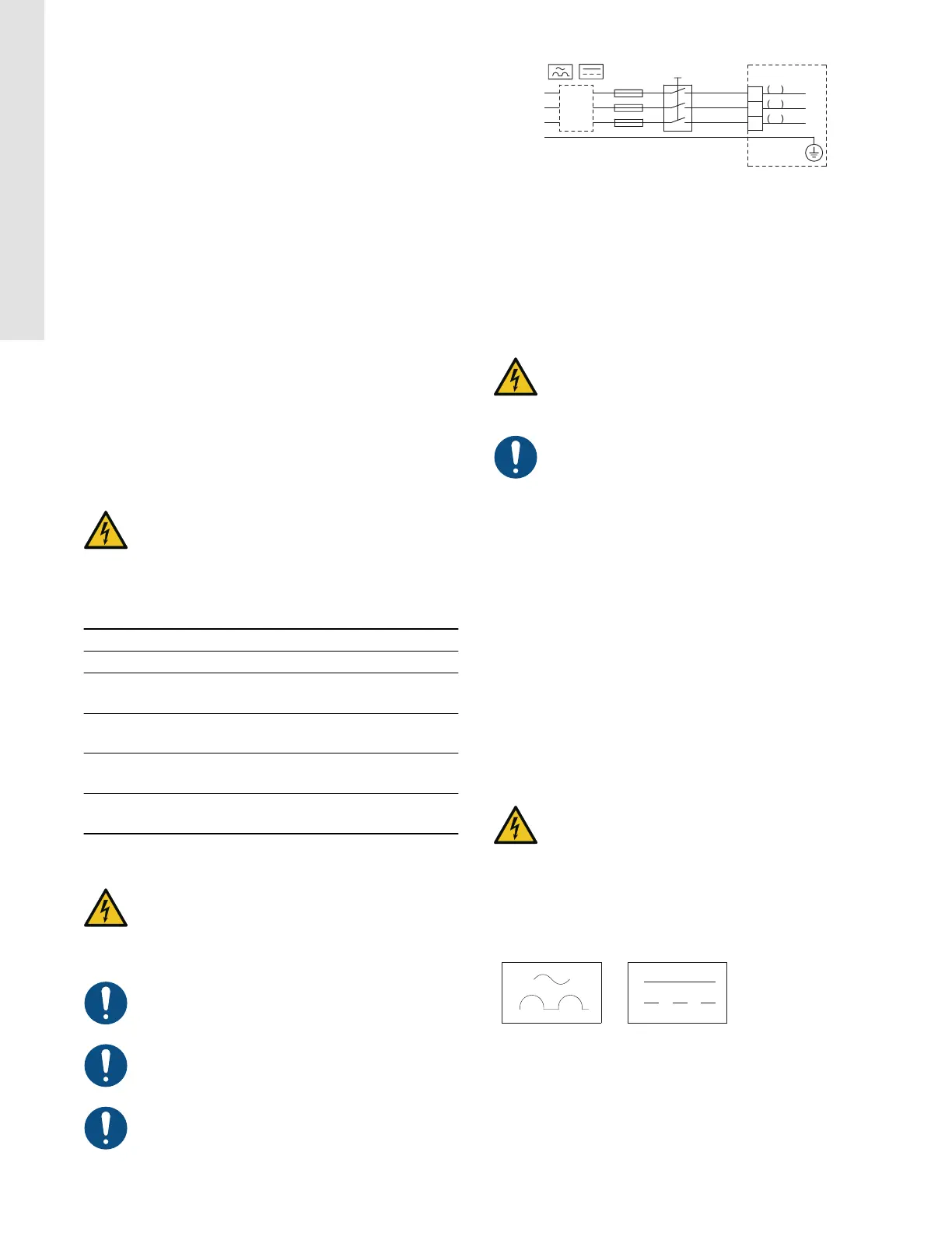
L1
L2
L3
PE
ELCB
L1
L2
L3
PE
91
92
93
TM038525
Example of three-phase mains connection of CUE with main
switch, backup fuses and additional protection
Related information
4. Installation requirements
6.1 Electrical protection
6.1.1 Protection against electric shock, indirect contact
CAUTION
Electric shock
Minor or moderate personal injury
‐ CUE must be earthed correctly and protected against
indirect contact according to local regulations.
The leakage current to protective earth exceeds 3.5 mA,
and a reinforced earth connection is required.
Protective conductors must always have a yellow and green (PE) or
yellow, green and blue (PEN) colour marking.
Instructions according to EN IEC 61800-5-1:
• CUE must be stationary, installed permanently and connected
permanently to the mains supply.
• The protective earth connection must be carried out with
duplicate protective conductors or with a single reinforced
protective conductor with a cross-section of minimum 10 mm
2
.
6.1.2
Protection against short circuit, fuses
CUE and the supply system must be protected against short circuit.
Grundfos requires that the backup fuses mentioned in section
Cable cross-section to signal terminals are used for protection
against short circuit.
CUE offers complete short-circuit protection in case of a short
circuit on the motor output.
6.1.3
Additional protection
WARNING
Electric shock
Death or serious personal injury
‐ The leakage current to protective earth exceeds 3.5
mA.
If CUE is connected to an electrical installation where an
earth leakage circuit breaker (ELCB/RCD) is used as additional
protection, the circuit breaker must be of a type marked with the
following symbols:
ELCB/RCD
The circuit breaker is type B.
The total leakage current of all the electrical equipment in the
installation must be taken into account.
The leakage current of CUE in normal operation can be seen in
section Electrical data.
During startup and in asymmetrical supply systems, the leakage
current can be higher than normal and may cause the ELCB/RCD
to trip.
8
English (US)