8. Control functions
The display contrast can be adjusted by pressing [Status]
and then pressing [Up] or [Down].
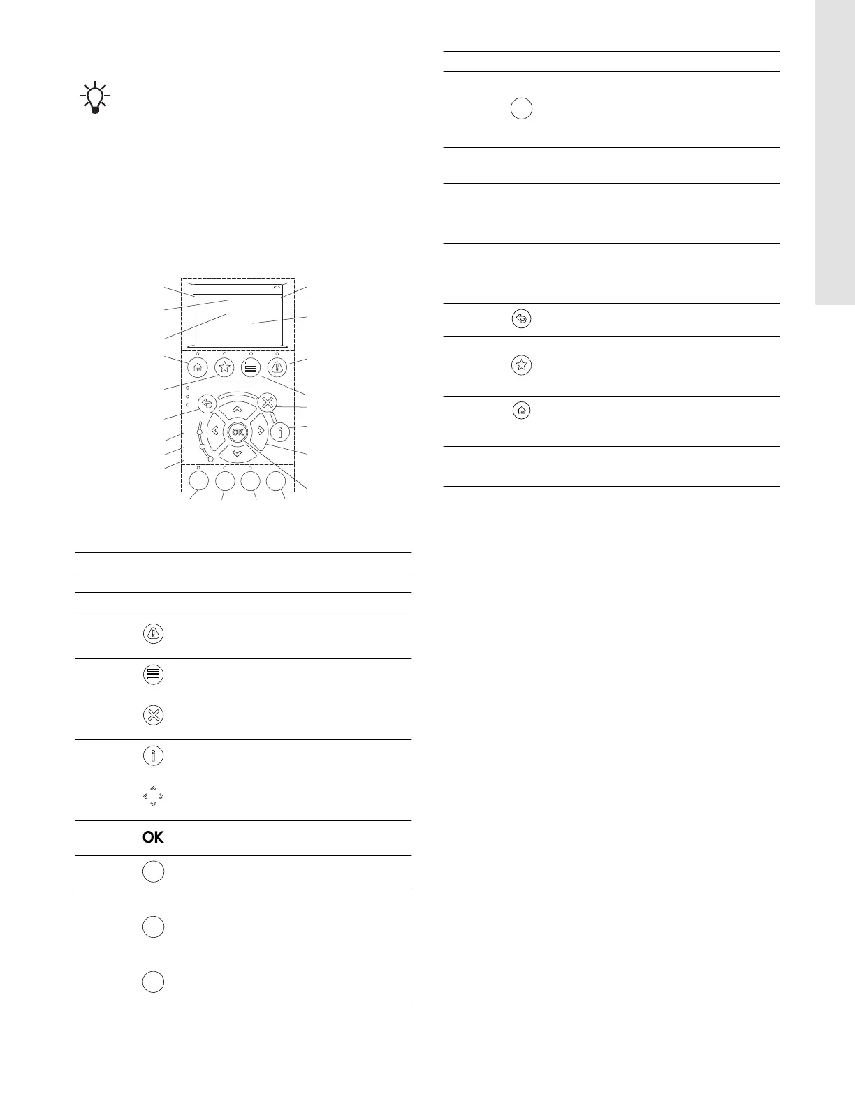
8.1 Operating panel
The operating panel consists of a display and several buttons.
It enables manual setting and monitoring of the system, such as
follows:
• Start, stop and control of speed.
• Reading of operating data and warnings and alarms.
• Setting functions for the frequency converter.
• Manual reset of the frequency converter.
1
AUTO
ON
RESET
HAND
ON
OFF
Status
1(1)
36.4 kW
Auto Remote Ramping
0.000
ON
ALARM
WARN.
7.83 A
799 RPM
53.2 %
2
3
4
5
6
7
8
9101112
13
14
15
16
17
18
19
20
21
TM074597
Operating panel
Pos. Buttons Description
1 Power [kW]
2 Reference [%]
3
[Alarm log]: shows a list of current
warnings, the last 10 alarms and the
maintenance log.
4
[Main menu]: allows access to all
programming settings.
5
[Cancel]: cancels the last change or
command as long as the display mode has
not changed.
6
[Info]: press for a definition of the function
being displayed.
7
[Up]/[Down]/[Left]/[Right]: use the four
arrow buttons to navigate between items in
the menu.
8
[OK]: used to access parameter groups or
to accept a selection.
9
[RESET]: resets the frequency converter
manually after a fault has been cleared.
10
[AUTO ON]: puts the system in remote
operational mode.
• Responds to an external start command
by control terminals or serial
communication.
11
[OFF]: stops the motor but does not
remove power to the frequency converter.
Pos. Buttons Description
12
[HAND ON]: starts the frequency converter
in local control.
• An external stop signal by control input or
serial communication overrides the local
[Hand On] function.
13
[Alarm]
Red
A fault condition causes the red alarm light
to flash and an alarm text is displayed.
14
[Warn.]
Yellow
When warning conditions are met, the
yellow warning light comes on and text
appears in the display area identifying the
problem.
15
[On]
Green
The On light activates when the frequency
converter receives power from the mains
voltage, a DC bus terminal or an external
24 V supply.
16
[Back]: reverts to the previous step or list
in the menu structure.
17
[Favourites]: allows access to
programming parameters for initial set-up
instructions and many detailed application
instructions.
18 [Status]: shows operational information.
19 Frequency
20 Motor current
21 Speed, RPM
8.2 Menu overview
Overview of the main menus. The ** represents a number to a
submenu.
• "0-** Operation / Display"
• "1-** Load and Motor"
• "2-** Brakes"
• "3-** Reference / Ramps"
• "4-** Limits / Warnings"
• "5-** Digital In/Out"
• "6-** Analog In/Out"
• "8-** Comm.and Options"
• "14-** Special Functions"
• "15-** Drive Information"
• "16-** Data Readouts"
• "18-** Info & Readouts"
• "20-** Drive Closed Loop"
• "21-** Ext. Closed Loop"
• "22-** Appl. Functions"
• "23-** Timer-based Functions"
• "27-** Cascade CTL Option"
• "29-** Water Application Functions"
• "30-** Special Features"
• "35-** Sensor Input Option"
• "200 - Operation Settings"
• "201- Key Functions"
• "202 - Sensors"
• "203 - Status Monitor"
19
English (US)