6.7 Connecting the signal relays
As a precaution, signal cables must be separated from
other groups by reinforced insulation in their entire
lengths.
R1
R2
03
02
01
06 05
04
NC 1
N0 1
C1
NC 2
N0 2
C2
TM038801
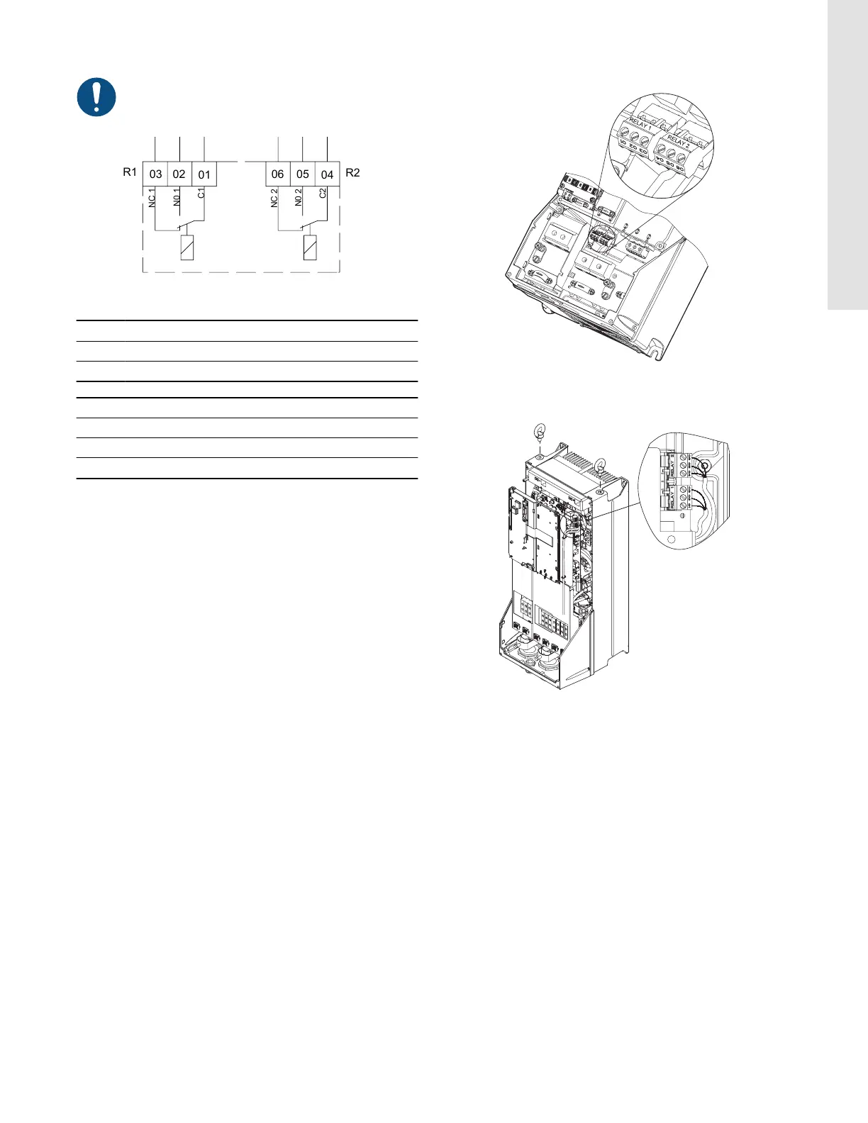
Terminals for signal relays in normal state (not activated)
Pos. Description
R1 RELAY 1
R2 RELAY 2
Terminal Function
C 1 C 2 Common
NO 1 NO 2 Normally open contact
NC 1 NC 2 Normally closed contact
Related information
6.5.1 Restart behaviour after STO activation
6.7.1
Access to signal relays
The relay outputs are positioned as shown in below figures.
TM039008
Terminals for relay connection, A5, B1 and
B2
TM039009
Terminals for relay connection, C1 and C2
17
English (US)