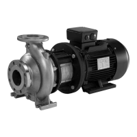
6.6.2 Access to signal terminals
All signal terminals are behind the terminal cover of the CUE front.
Remove the terminal cover as shown in the figure below.
TM039004
Access to signal terminals
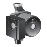
TM039025
Signal terminals, all enclosures
6.6.3 Fitting the conductor
1. Remove the insulation at a length of 9 to 10 mm.
2. Insert a screwdriver with a tip of maximum 0.4 × 2.5 mm into the
square hole.
3. Insert the conductor into the corresponding round hole. Remove
the screwdriver. The conductor is now fixed in the terminal.
TM039026
Fitting the conductor into the signal terminal
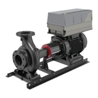
6.6.4 Setting the analog inputs, terminals 53 and 54
Contacts A53 and A54 are positioned behind the operating panel
and used for setting the signal type of the two analog inputs.
The factory setting of the inputs for non-sensor version pump is "U"
and "U". The factory setting of sensor version pump is "U" and "I".
If a 0/4-20 mA sensor is connected to terminal 54, the
input must be set to current signal "I".
Switch off the power supply before setting contact A54.
Remove the operating panel to set the contact. See the figure
below.
TM039104
Setting contact A54 to current signal "I"
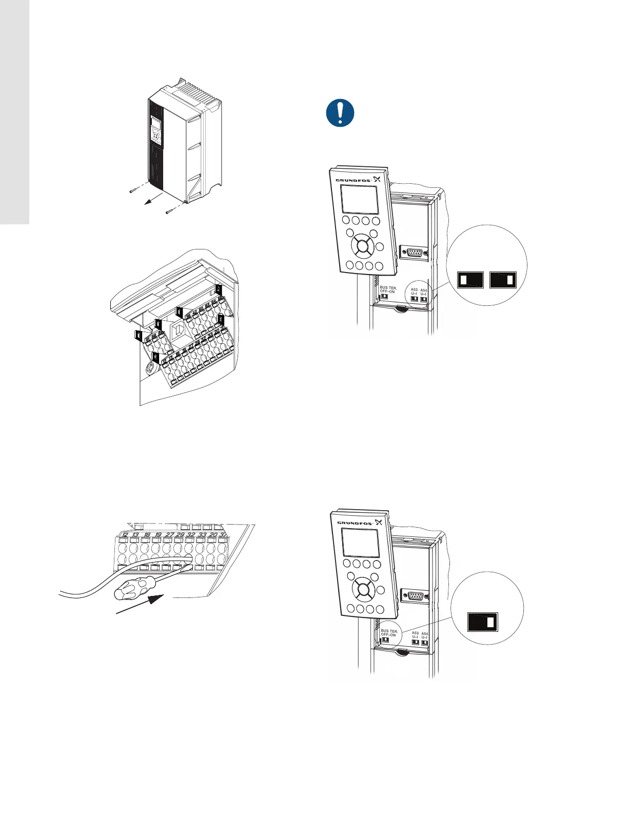
6.6.5 RS-485 GENIbus network connection
One or more CUE units can be connected to a control unit via
GENIbus.
The reference potential, GND, for RS-485 (Y) communication must
be connected to terminal 61.
If more than one CUE unit is connected to a GENIbus network, the
termination contact of the last CUE must be set to ON (termination
of the RS-485 port).
The factory setting of the termination contact is OFF (not
terminated).
Remove the operating panel to set the contact. See the figure
below.
TM039006
Setting the termination contact to ON
16
English (US)