TM051507
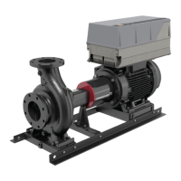
External setpoint, current input
39 42
50
53
54
55
61 68
69
61 68
69
12 13
18
19
27
29
32
33
20
37
A53
U
I
U
I
A54
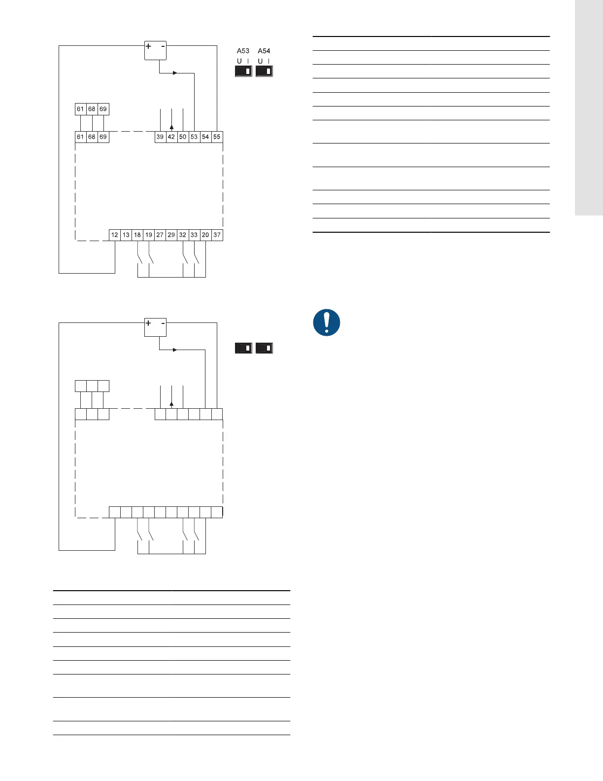
TM075269
3-wire sensor
Terminal Type Function
12 +24 V out Supply to sensor
13 +24 V out Additional supply
18 DI 1 Digital input, programmable
19 DI 2 Digital input, programmable
20 GND Common frame for digital inputs
27 DI/O 1
Digital input/output,
programmable
29 DI/O 2
Digital input/output,
programmable
32 DI 3 Digital input, programmable
Terminal Type Function
33 DI 4 Digital input, programmable
37 Safe stop Safe stop
39 GND Frame for analog output
42 AO 1 Analog output, 0-20 mA
50 +10 V out Supply to potentiometer
53 AI 1
External setpoint, 0-10 V, 0/4-20
mA
54 AI 2
Sensor input, sensor 1, 0/4-20
mA
55 GND
Common frame for analog
inputs
61 RS-485 GND Y GENIbus, frame
68 RS-485 A GENIbus, signal A (+)
69 RS-485 B GENIbus, signal B (-)
Default connections made in NBE, NKE, NBSE:
• DI1 connected to GND.
Default connections made in NBE, NKE, NBSE Series 2000:
• DI1 connected to GND
• A three-wire sensor is connected to terminal 12, 54 and 55.
The RS-485 screen must be connected to the frame.
15
English (US)