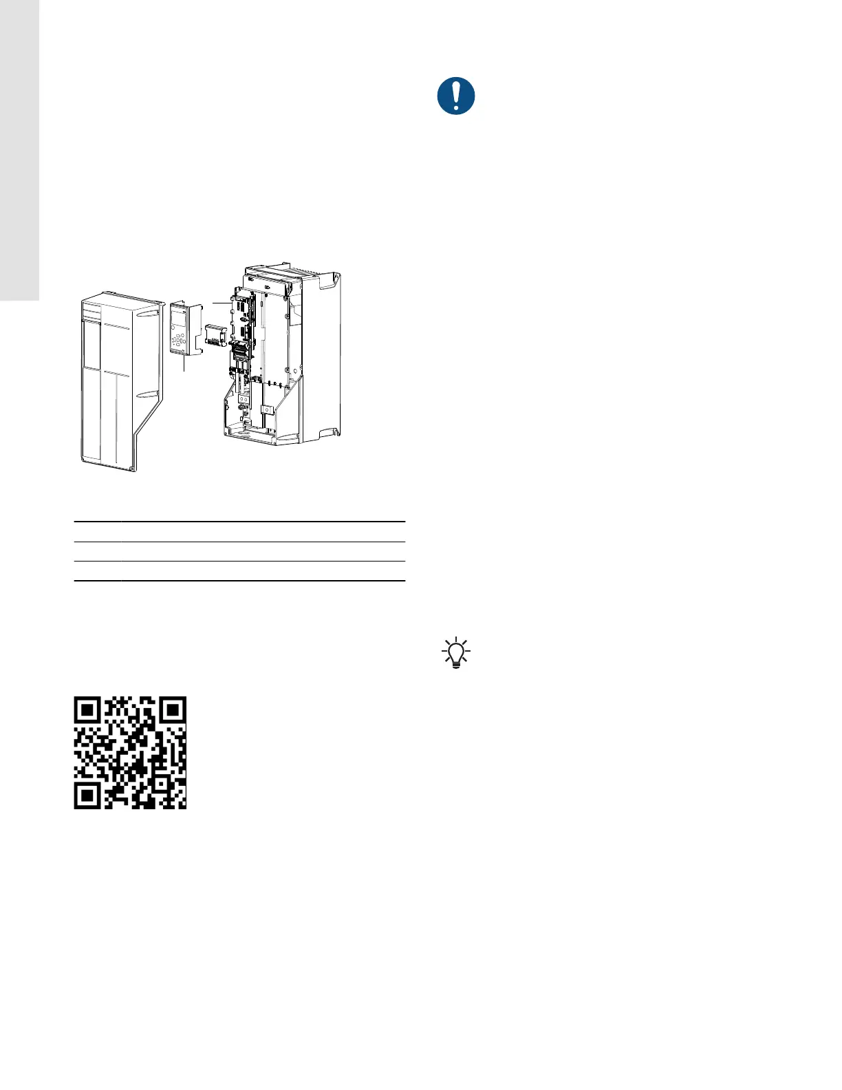
6.7.2 Fitting MCB 114 in CUE
Enclosures A5, B1, B2, C1, C2
1. Switch off the power to CUE. See section RFI filter type is
according to EN 61800-3.
2. Remove the operating panel and the cradle from CUE. See the
figure below.
3. Fit MCB 114 into port B.
4. Connect the signal cables, and fasten the cables with the
enclosed cable strips. See the figure below.
5. Fit the cradle and the operating panel.
6. Connect power to CUE.
TM040027
Enclosures B2, C1
Pos. Description
1 Cradle
2 Port B
Related information
6.3 RFI filters
6.8 BACnet MS/TP connection
Grundfos CUE has integrated BACnet MS/TP. For detailed
configuration, go to https://www.grundfos-eica.com or scan the QR
code.
7. Starting up the product
Any installation, maintenance and inspection must be
carried out by qualified, experienced and authorized
persons.
Before you switch on the power supply, you must do the following:
• Close the cover.
• Ensure that all cable glands are tightened properly.
• Check that there are no loose connections on the terminals.
• Confirm that the supply voltage matches the voltage of the
frequency converter and the motor.
7.1 Switching on the product
• Confirm that the input voltage is balanced within 3 %. If not,
correct the input-voltage imbalance before proceeding. Repeat
this procedure after the voltage correction.
• Ensure that any optional equipment wiring matches the
installation application.
• Ensure that all operator devices are in the OFF position.
• Apply power to the unit, but do not start the frequency converter
yet. For units with a disconnect switch, turn it to the ON position
to apply power to the frequency converter.
7.2 Activating the optional STO function
The STO function is activated by removing the voltage at terminal
37 of the frequency converter. By connecting the frequency
converter to external safety devices providing a safe delay, an
installation for a Safe Stop 1 is obtained. External safety devices
need to fulfill Cat./PL or SIL when connected to terminal 37.
The STO function can be used for the following motor types:
• asynchronous
• synchronous
• permanent magnet motors.
When terminal 37 is activated, the frequency converter issues an
alarm, trips the unit and coasts the motor to a stop. A manual
restart is required. Use the STO function to stop the frequency
converter in emergency stop situations. In normal operating mode,
the STO terminal 37 must be deactivated to start the motor.
A successful commissioning test of the STO function is
required after the initial installation and after each
subsequent change to the installation.
18
English (US)